


6–6EPSONS1F70000 Series
Technical Manual
Appendix
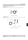
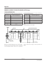
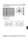
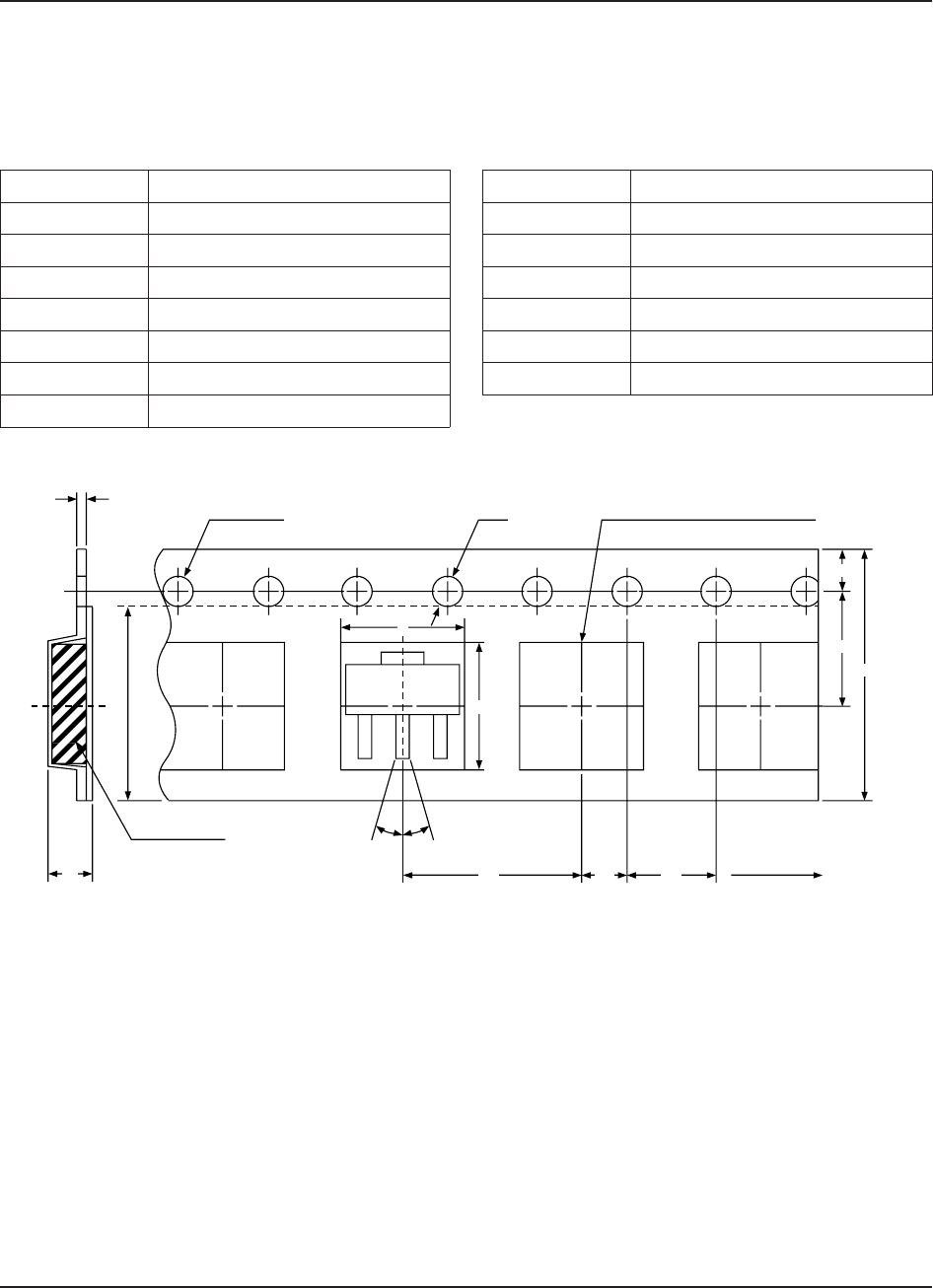
TAPING INFORMATION
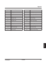
The emboss carrier taping standard is shown in the
following table and figure. This standard conforms to
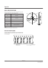
Dimension code Dimensions/angles (mm/°)
A 5.0
B 4.6
D 1.5 +0.1, –0.05
E 1.50 ±0.1
F 5.65 ±0.05
P1 8.0 ±0.1
P0 4.0 ±0.1
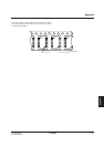
Dimension code Dimensions/angles (mm/°)
P2 2.0 ±0.05
T 0.3
T2 2.3
W 12.0 ±0.2
W1 9.5
θ 30°Max.
There are no joints in either the cover or carrier tapes.
Less than 0.2% of the total device count is comprised
of non-sequential blanks. There are no sequential
blanks. This does not apply to the tape leader and
trailer.
Note
The tape thickness is 0.1 mm Max.
the EIAJ RCI00B electronic parts taping specification.
Each tape holds 1,000 devices.
Device cavity
T2
T
D
Feeder hole Cross section with device position
Travel direction
E
F
B
θθ
A
W
P1 P0P2
EMBOSS CARRIER TAPING STANDARD (SOT89-3pin)