


DGS-22 Issue 02, 03/99 Krautkramer USN 52R/USN 52L Option DGS
H Note:
There are 13 probes with the corresponding parameters
stored in the unit. You can enter a probe of your own at
probe number 16, please refer to Storing a new probe,
Chapter 3.
H Note:
All of the following parameters must be programmed in
order to generate a DGS curve.
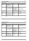
– Enter the shape of the reference reflector in the
REF-ECHO function.
– Enter the size of the reference reflector.
If you have selected Backwall as the shape of the ref-
erence reflector, the size of the reference reflector is
automatically infinite.
H Note:
The adjustable size of the reference reflector depends
on the probe. The minimum size permitted is 5 % of the
element diameter.
– Enter the sound attenuation in the reference block in
the ATT-REF function.
– Enter the sound attenuation in the test object in the
ATT-TEST function.
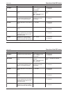
– Enter a value for the amplitude correction for angle-
beam probes in the AMPL-COR function (correction
value as per data sheet).
The following reference blocks are available for angle-
beam probes:
• Reference echo for 2 MHz probes is the echo from
the 100mm circular arc of the calibration block 1.
• Reference echo for 4 MHz (MWB...) probes is the
echo from the 25 mm circular arc of the calibration
block 2.
– Enter a value for the transfer loss in the
T-CORRECTION function.
A Attention:
When entering the transfer loss value it is important to
note the following:
This value indicates changes in sensitivity (in dB) for
the evaluation of discontinuities when the reference
block and the test object have different coupling condi-
tions (surface roughness and/or curvature).
Operating the DGS Preparing the DGS evaluation
DGS-22 Issue 02, 03/99 Krautkramer USN 52R/USN 52L Option DGS
H Note:
There are 13 probes with the corresponding parameters
stored in the unit. You can enter a probe of your own at
probe number 16, please refer to Storing a new probe,
Chapter 3.
H Note:
All of the following parameters must be programmed in
order to generate a DGS curve.
– Enter the shape of the reference reflector in the
REF-ECHO function.
– Enter the size of the reference reflector.
If you have selected Backwall as the shape of the ref-
erence reflector, the size of the reference reflector is
automatically infinite.
H Note:
The adjustable size of the reference reflector depends
on the probe. The minimum size permitted is 5 % of the
element diameter.
– Enter the sound attenuation in the reference block in
the ATT-REF function.
– Enter the sound attenuation in the test object in the
ATT-TEST function.
– Enter a value for the amplitude correction for angle-
beam probes in the AMPL-COR function (correction
value as per data sheet).
The following reference blocks are available for angle-
beam probes:
• Reference echo for 2 MHz probes is the echo from
the 100mm circular arc of the calibration block 1.
• Reference echo for 4 MHz (MWB...) probes is the
echo from the 25 mm circular arc of the calibration
block 2.
– Enter a value for the transfer loss in the
T-CORRECTION function.
A Attention:
When entering the transfer loss value it is important to
note the following:
This value indicates changes in sensitivity (in dB) for
the evaluation of discontinuities when the reference
block and the test object have different coupling condi-
tions (surface roughness and/or curvature).
Operating the DGS Preparing the DGS evaluation