


Krautkramer USN 52R/USN 52L Issue 05, 02/00 5-21
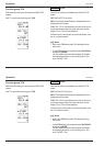
Example:
Calibration on a semicylinder having a radius of
R=50 mm at a test range of 200 mm.
– Set RANGE to 200 mm.
– Set DELAY and ZERO to 0.
– Set MEASURE to MULTECHO.
– Couple the probe and peak the echoes.
– Adjust the gate so that the first arc echo (® 50 mm
sound path) in Gate a and the second arc echo
(® 150 mm sound path) in Gate b are evaluated.
– Set the sound velocity MTL VEL so that
“S=100" is displayed in the measurement line
– Set MEASURE to 0 TO 1st
– Set Gate a to an echo
– Set ZERO so that “S=50" is displayed in the
measurement line
The calibration has now been completed.
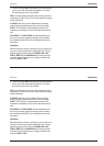
Calibration with a dual (T/R) probe
Above all, dual (T/R) probes are mainly used for thick-
ness measurement. When applying these probes ob-
serve the following characteristics:
The FLANK mode
Most dual (T/R) probes have a roof angle (an element
which is at an angle to the surface of the test object).
Due to this, mode conversions occur with sound entry
and at the reflection on the backwall which can cause
rugged, wide echoes. This is the reason why you should
always select FLANK in TOF.
In order to obtain steep increasing flanks, which enable
a higher measurement accuracy, you can use the Re-
ject function if necessary. In this regard, refer to the
information on the DAMPING function.
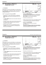
V-path error
With dual (T/R) probes, there is a V-shaped sound path
from the pulser to the receiver element via the reflec-
tion from the backwall. This “V-path” influences the
measurement accuracy. Therefore, you should select
two thicknesses which include the expected thickness
range. The V-path error can be largely compensated in
this way.
USN 52 R calibration Operation
Krautkramer USN 52R/USN 52L Issue 05, 02/00 5-21
Example:
Calibration on a semicylinder having a radius of
R=50 mm at a test range of 200 mm.
– Set RANGE to 200 mm.
– Set DELAY and ZERO to 0.
– Set MEASURE to MULTECHO.
– Couple the probe and peak the echoes.
– Adjust the gate so that the first arc echo (® 50 mm
sound path) in Gate a and the second arc echo
(® 150 mm sound path) in Gate b are evaluated.
– Set the sound velocity MTL VEL so that
“S=100" is displayed in the measurement line
– Set MEASURE to 0 TO 1st
– Set Gate a to an echo
– Set ZERO so that “S=50" is displayed in the
measurement line
The calibration has now been completed.
Calibration with a dual (T/R) probe
Above all, dual (T/R) probes are mainly used for thick-
ness measurement. When applying these probes ob-
serve the following characteristics:
The FLANK mode
Most dual (T/R) probes have a roof angle (an element
which is at an angle to the surface of the test object).
Due to this, mode conversions occur with sound entry
and at the reflection on the backwall which can cause
rugged, wide echoes. This is the reason why you should
always select FLANK in TOF.
In order to obtain steep increasing flanks, which enable
a higher measurement accuracy, you can use the Re-
ject function if necessary. In this regard, refer to the
information on the DAMPING function.
V-path error
With dual (T/R) probes, there is a V-shaped sound path
from the pulser to the receiver element via the reflec-
tion from the backwall. This “V-path” influences the
measurement accuracy. Therefore, you should select
two thicknesses which include the expected thickness
range. The V-path error can be largely compensated in
this way.
USN 52 R calibration Operation