


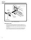


Additional Considerations
Using Shielded Wiring
5
5-11
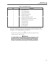
• Avoid connecting inputs with ac volts signals to any channel 10 numbers away from
a sensitive channel (i.e. 4-terminal input channels.)
• Avoid tying L (low) or (especially) H (high) inputs of a sensitive channel to earth
(chassis) ground. This is very important in resistance measurements.
• Avoid high source impedances on sensitive channels, or minimize the capacitance of
the sensitive channel to earth (chassis) ground for high impedance inputs.
• Whenever high ohms measurements (> 10 kΩ) must be made accurately, avoid
connecting any inputs carrying ac volts signals to the Hydra Series II instrument.
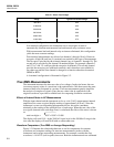
Note
If frequencies other than 50 or 60 Hz must be present on other channels
while measuring resistance, temperature, or dc voltage, frequencies of 40
Hz + multiples of 80 Hz (40, 120, 200, etc.) up to 2 kHz should be avoided.
Otherwise, frequencies at intervals of 5 Hz will generally contribute no
more error to a resistance measurement than frequencies of 50 or 60 Hz.
It is not necessary to follow all of these guidelines. In fact, for most applications,
adhering to just one of these guidelines will provide satisfactory results. Refer to
Appendix D for detailed information about cross talk.
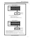
Using Shielded Wiring
Shielded wires and sensors, such as sheathed thermocouples, are often used in noisy
environments to reduce measurement errors. When you are connecting these sensors to a
measuring instrument, the proper connection of the shield depends on the entire
measurement system and environment.
General Rule
Connect the shield to L (low) at the input terminals for each Hydra Series II channel.
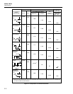
Alternate Suggestions
In specific instances, following the General Rule may not result in the optimum noise
rejection; it may be necessary to try alternate configurations and check for improved
performance.
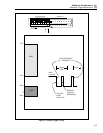
Non-Isolated Sensor Configuration
If non-isolated sensors are used, (e.g. a thermocouple probe where the sensor and its
shield are electrically connected), try leaving the shield disconnected (open) at the
2620A-100 Input Module.
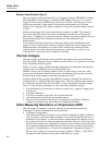
Isolated and Shielded Sensor Configuration
WWarning
The following suggestions rely on the shield being kept
electrically isolated from the sensor h (high) and l (low)wiring,
except where specifically stated otherwise
If isolated and shielded sensors are used with the instrument, (e.g., an isolated
thermocouple probe where the thermocouple junction is electrically isolated from
shield), two additional configurations to try are: