2620A, 2625A
Users Manual
3-4
Other Displayed Data
An array of "MIN", "MAX", and "LAST" values for each channel is updated whenever
scan measurements are taken. This Review array can be displayed from Active or
Inactive (but not Configuration) Mode by pressing N.
The constantly updated Totalizer count can also be displayed (Active or Inactive Mode
only) by pressing O.
Note that either the Review array or the Totalizer count can be displayed at one time;
you must deactivate one before activating the other. Deactivate the Review array by
pressing N a second time. Deactivate the Totalizer display by pressing O a second
time. Pressing C also deactivates either function.
What is the Present Configuration?
If Power is Interrupted
All configuration settings (function, range, scan interval, etc.) are stored in nonvolatile
memory. If power is interrupted (R pressed off or due to power loss), these settings
are retained. When turned on, the instrument first executes a self test, then resumes the
state it was in prior to interruption of power. This feature is handy for applications where
power may be inadvertently lost; the instrument automatically resumes taking
measurements, as originally configured, once power is restored.
If the Configuration is Reset
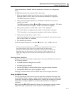
You can perform a Configuration Reset in either of two ways:
• From the front panel, press and hold
when cycling POWER ON.
• Through the computer interface, send the *RST command.
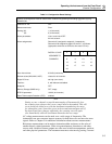
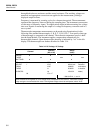
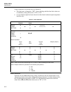
Refer to Table 3-1 for the configuration reset settings.
Channel Configuration
Configuration Mode involves selecting an entry from a list of choices (and may involve
setting number values.) Measurements are not taken when the instrument is in
Configuration Mode. Configuration Mode is discussed throughout this chapter; it is used
whenever a parameter for a channel or for the whole instrument needs to be set.
Selecting Channel, Function, and Range
Steps necessary for setting each type of measurement function are shown in the
following tables:
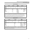
• DC Voltage Measurement (Table 3-2)
• AC Voltage Measurement (Table 3-2)
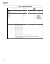
• Resistance Measurement (Table 3-3)
• Frequency Measurement (Table 3-4)
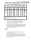
• Temperature Measurement Using Thermocouples (Table 3-5)
• Temperature Measurement Using RTDs (Table 3-6)
Additional channel configuration steps (alarms, scaling, etc) are discussed later in this
chapter.


