


2620A/2625A
Users Manual
C-2
Measurement rate: Slow.
Scaling (M):1 (all channels)
Offset (B): 0 (all channels)
Alarm parameters: Limit-1 and Limit-2 OFF. All limit values 0.
Alarm assignments: Channels 0-3 assigned to outputs 0-3,respectively.
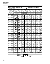
Channels 4-20 assigned to digital
I/O lines 4-7, as shown in Table 3-8.
Scan interval time: 0:00:00 (continuous)
Review values (MIN, MAX, LAST) cleared for all channels.
Digital I/O lines: high (non-alarm)
Totalizer: 0, with debounce disabled.
Autoprint/Memory Storage: OFF.
RTD R0 parameter: 100.00 (all channels)
Open Thermocouple Detection (OTC) enabled.
5. A description of message exchange options:
The size and behavior of the input buffer.
The input buffer size is 350 bytes. If the input buffer fills, the IEEE-488.1
bus will be held off until there is room in the buffer for a new byte.
Which queries return more than one <RESPONSE MESSAGE UNIT>, Section
6.4.3.
The following queries always return more than one <RESPONSE
MESSAGE UNIT>:
LOG?, NEXT?, INTVL?, TIME_DATE?, PRINT_TYPE?, *IDN?, SCAN_TIME?,
SCALE_MB?
The following queries may return more than one <RESPONSE MESSAGE
UNIT>:
FUNC?, MIN?, MAX?, LAST?, ALARMS?, RANGE?,ALARM_LIMIT?
Which queries generate a response when parsed, Section 6.4.5.4.
All queries generate a response when parsed.
Which queries generate a response when read, Section 6.4.5.4.
No queries generate a response when read by the controller.
Which commands are coupled, Section 6.4.5.3.
No commands are coupled.
6. A list of functional elements used in constructing device-specific commands.
Whether <compound command program header> elements are used must also be
included, Section 7.1.1 and 7.3.3.
Device-specific commands used:
<PROGRAM MESSAGE>
<PROGRAM MESSAGE TERMINATOR>