Using the Computer Interface
General Information (RS-232 and IEEE-488)
4
4-17
loaded, the Message Available (MAV) bit in the Status Byte Register is set true. (For
more information, see "Status Byte Register" later in this chapter.)
Numeric output from the instrument is returned as shown in the following examples:
• Integer Values Examples
3 In response to RANGE? query, range is 3 for the selected function.
0 In response to ALARMS? query, there are no alarms on this channel.
• Scientific Notation Values
+1.2345E+6 Measured value of 1.2345 X 10
6
+12.345E+6 OHM Measured value of 12.345 X 10
6
ohms (format 2)
+1E+9 Positive overload (“OL” appears on the display).
-1E+9 Negative overload (“-OL” appears on the display).
+9E+9 Open thermocouple indication (“otc” appears on the display).
Service Requests (IEEE-488 only) and Status Registers
Service requests let an instrument on the IEEE-488 bus get the attention of the host.
Service requests are sent over the service request (SRQ) line.
Note
If the instruments is in the remote state without front panel lockout (i.e.,
REMS), a service request can be sent from the front panel by pressing (up
button picture).
If more than one instrument on the bus is capable of sending service requests, the host
can determine which instrument made the request by taking a "serial poll". Each
instrument on the bus responds to the poll by sending the contents of its Status Byte
Register (STB). If an instrument on the bus has made a service request, the request
service bit (RQS, bit 6) of its Status Byte Register (STB) will be set to 1, identifying it as
an instrument that requested service.
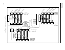
The contents of the Status Byte Register (STB) are defined by the Service Request
Enable Register (SRE), Event Status Register (ESR), Event Status Enable Register
(ESE), and the output buffer. These status registers are discussed in the following
paragraphs. Figure 4-4 shows the relationship of these registers.


