2620A, 2625A
Users Manual
3-12
At any Configuration Reset (power up C or computer interface *RST), alarm limits on
channels 4 through 20 are assigned to Digital I/O lines 4 through 7 in the "ORed" pattern
shown in Table 3-8. These assignments can be changed via the Computer Interface. Each
limit (S or T) for a channel can be assigned to any one digital output.
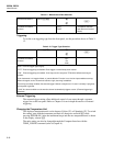
Table 3-8. Initial Alarm Assignments, Digital I/O Lines 4 Through 7
Digital I/O Line 4567
Assigned to Channels 4567
891011
12 13 14 15
16 17 18 19
20
(Appropriate channels are OR’ed to drive each I/O line.)
All Digital I/O lines are set high (non-active) whenever power is cycled. These lines
remain high until a new scan detects an alarm condition on an assigned limit or until a
new Computer Interface command is received.
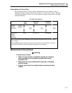
Note
Measurements taken with the Monitor function do not affect the digital
outputs.
At the completion of a scan, an alarm condition sets the assigned digital output to a logic
0 (low) state. The digital output returns to a logic 1 (high) state when all assigned alarm
conditions are cleared. Note that digital outputs for alarms are updated only at the end of
each scan. This technique prevents unnecessary toggling of the digital lines during a
scan.
Mx+B Scaling
Any analog input channel (0 through 20) can be assigned scaling ("M" and "B") values
that are applied to subsequent measurements of that channel. Scaling values can be set
via the front panel or over a computer interface.
The "M" value is used as a multiplier of the actual reading; the "B" value is then added
in the same units as the resultant. If no scaling values are specified for a channel, the
Configuration Reset values of 1 ("M") and 0 ("B") are used, leaving the measurement
reading unaltered.
In the Inactive Mode, the "Mx+B" annunciator lights to indicate that an M value other
than 1 and/or a B value other than 0 has been specified for the displayed channel. When
a measurement is displayed for a channel so configured, no measurement units ("Ω",
"V", etc.) are shown.
Note
If you press B for a channel that is OFF, an error beep will result.
Always use F to define the channel’s measurement function before using
B to define the scaling values.
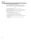
You can familiarize yourself with the Mx+B setup procedure by pressing B. Then
press E a few times to cycle through the elements of the scaling values. If only
E is pressed, no changes are introduced. Note that the scaling value element that can


