


2620A, 2625A
Users Manual
3-20
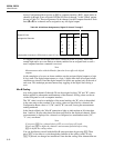
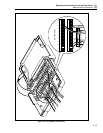
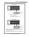
Resistance and RTD
For all channels (0 through 20), 2-terminal resistance or RTD measurements are allowed.
Four-terminal measurements can be made on channels 1 through 10 only. Refer to
Figure 3-3.
For each channel configured for 4-terminal measurements (channels 1-10 only), a second
channel (numbered 10 higher than the first) becomes unavailable for any other type of
measurement. For example, using channel 7 to make 4-terminal resistance measurements
requires the use of input terminals for both channels 7 and 17. Channel 17 cannot be
used to take any other measurements as long as channel 7 remains configured for 4-
terminal measurements.
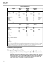
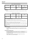
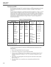
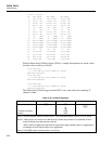
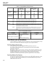
Table 3-14. Thermocouple Ranges
Positive Lead Positive Lead Color Negative Lead* Usable Range
Type Material (ANSI) (IEC) Material (°C)
J Iron WHITE BLACK Constantan -210 to 760
K Chromel YELLPW GREEN Alumel -270 to 1372
E Chromel PURPLE VIOLET Constantan -270 to 1000
T Copper BLUE BROWN Constantan -270 to 400
N NISIL-
NOCROSIL
-270 to 1300
R Platinum BLACK ORANGE Platinum
(13% Rhodium)
0 to 1767
S Platinum BLACK ORANGE Platinum
(10% Rhodium)
0 to 1767
B Platinum
(30% Rhodium)
GRAY Platinum
(6% Rhodium)
0 to 1820
C** Tungsten WHITE Tungsten
(26% Rhenium)
0 to 2316
* ANSI negative lead always RED, IEC negative lead always WHITE
** Hoskins Engineering Co.
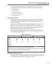
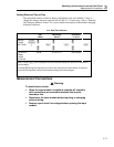
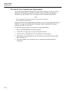
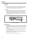
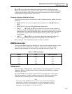
Use the following procedure for resistance or RTD measurement connections to the
Input Module:
1. Remove the Input Module from the rear panel.
2. Loosen the two large screws on top and open the module.
3. Connect wires to H (high) and L (low) terminals for each channel (channel 7 for 2-
terminal configuration or channels 7 and 17 for 4-terminal configuration, in this
example.)
4. Thread these wires through the strain-relief pins and out the back of the module.
Refer to Figure 3-2.
5. Close the module cover, secure the screws, and put the module back in the
instrument.