


Using the Computer Interface
Computer Interface Command Set
4
4-29
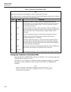
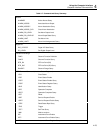
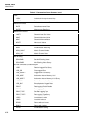
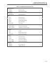
Table 4-8. Command and Query Reference (cont)
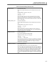
ALARM_ASSOC? Alarm Association Query
Returns alarm output associations for the indicated channel and alarm
limit.
ALARM_ASSOC? <channel>,<limit_num>
<channel> = (4 .. 20)
<limit_num> = 1 2
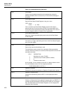
Returns the digital output line number associated with the indicated
alarm limit. An Execution Error is generated if no output is associated
with this alarm limit, if invalid channel numbers are used, or if limits other
than 1 or 2 are used.
ALARM_ASSOC_CLR Clear Alarm Association
Clear the digital output association for the indicated channel and alarm
limit.
ALARM_ASSOC_CLR <channel>,<limit_num>
<channel> = (4 .. 20)
<limit_num> = 1 2
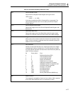
When the association is cleared, the output pin is left in a high (non-
alarm) state. If the alarm limit specified is not 1 or 2, or if the channel is
invalid, an Execution Error is generated.
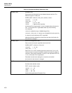
ALARM_DO_LEVEL Set Alarm Output Level
Set or clear the indicated alarm digital output.
ALARM_DO_LEVEL <DO_line>,<DO_state>
<DO_line> = (0 .. 3)
<DO_state> = 1 (high) 0 (low)
Alarm outputs 0-3 correspond to channels 0-3, respectively. If the digital
output line requested is not in the range 0 through 3, an Execution Error
is generated. If the DO_state specified is not 1 (high) or 0 (low), an
Execution Error is generated.
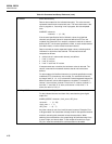
ALARM_DO_LEVELS? Alarm Output State Query
Returns digital output levels for the four alarm digital outputs.
Returns an integer value representing the state of each of the digital I/O
lines. The low order four bits are the status of the alarm digital outputs; 0
indicates line is low (in alarm), and 1 indicates line is high (not in alarm).
These lowest four bits correspond to alarm digital outputs 0 through 3,
which are permanently associated to channels 0 through 3, respectively.
A value of 15 indicates that all alarm outputs are in the non-alarm (high)
state.