


2620A, 2625A
Users Manual
3-6
through both a known resistance and the sensed resistance. The resulting voltages are
measured and appropriate conversions are applied to the measurement, yielding a
displayed output in ohms.
Frequency is measured by counting cycles for a known time period. The measurement
represents the frequency observed during the sampling time. The instrument can measure
a wide range of frequency inputs. Test applications might include measuring line voltage
sine wave signals or measuring the output of a voltage-to-frequency converter used in a
servo system.
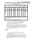
Thermocouple temperature measurements can be made using linearizations for the
following nine standard thermocouples: J, K, E, T, N, R, S, B, C. You specify what type
of thermocouple is connected to the channel. The reference temperature sensor is built
into the Input Module. The instrument applies compensation automatically for
thermocouple channels. Open thermocouple detection is indicated by "otc" in the left
display. The thermocouples are further described in Table 3-14.
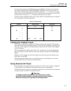
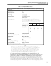
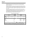
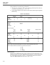
Table 3-2. DC Voltage, AC Voltage
Channel
Function
(DC or AC)
Range
(Note)
PRESS
THESE
BUTTONS:
TO
SELECT
FROM
THESE
CHOICES:
0
1
.
.
20
OFF
V DC
V AC
Ω
Hz
°C or °F
Auto
300.00 mV
3.0000V
30.000V
150.00*V
(Completes
Selection
and returns
to Inactive
Mode)
* 300.00 CH 0, 1, and 11
Note: Determine the highest ac or dc voltage value anticipated for this channel. Then select a range
large enough to accommodate this value. If the highest voltage cannot be anticipated, select “Auto”.