


Maintenance
Performance Tests
6
6-9
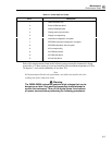
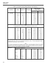
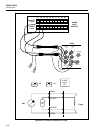
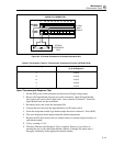
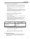
Table 6-3. Performance Tests (Voltage, Resistance, and Frequency) (cont)
Using inputs in decades of 1.9:
300 Ω short 0.00 0.09
190 Ω 189.93 190.12
3 kΩ short 0.0000 0.0003
1.9 kΩ 1.8992 1.9008
30 kΩ 19 kΩ 18.992 19.008
300 kΩ 190 kΩ 189.91 190.09
3 MΩ 1.9 MΩ 1.8983 1.9017
Using inputs in decades of 1:
300 Ω short 0.00 0.09
100 Ω 99. 95 100.10
3 kΩ short 0.0000 0.0003
3 kΩ 1 kΩ 0. 9995 1.0006
30 kΩ 10 kΩ 9. 995 10.005
300 kΩ 100 kΩ 99. 94 100.06
3 MΩ 1 mΩ 0. 9990 1.0010
10 MΩ* 10 MΩ 9. 979 10.021
*Optional test point if standards available.
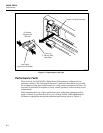
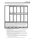
Note
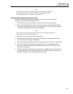
All channels (0 through 20) can accommodate 2-terminal resistance measurements. Channel 0, with only
two connections, cannot be used for 4-terminal measurements. Four-terminal resistance measurements
can be defined for channels 1 through 10 only. Channels 11 through 20 are used, as required, for 4-
terminal to provide the additional two connections. For example, a 4-terminal set up on channel 1 uses
channels 1 and 11, each channel providing two connections.
Frequency 90 kHz 10 kHz/2V p-p 9.994 10.006
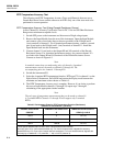
Thermocouple Measurement Range Accuracy Test
Assure the Accuracy Verification Test for channel 0 meets minimum acceptable levels
before performing this test.
Thermocouple temperature measurements are accomplished using Hydra Series II’s
internal 100 mV and 1V dc ranges. (The ranges are not configurable by the operator.)
This procedure will provide the means to test these ranges.
To test the 100 mV and 1V dc ranges requires computer interfacing with a host (terminal
or computer). The host must send commands to select these ranges. These ranges cannot
be selected from the front panel of Hydra Series II.
1. Ensure that communication parameters ( i.e., transmission mode, baud rate, parity,
and echo mode) on the Hydra Series II and the host are properly configured to send
and receive serial data. Refer to Chapter 4.
2. Power up Hydra Series II and allow it to temperature stabilize for 1/2 hour.