


Operating the Instrument from the Front Panel
Channel Configuration
3
3-5
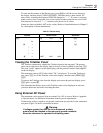
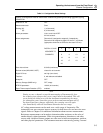
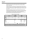
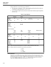
Table 3-1. Configuration Reset Settings
Perform a Configuration Reset to restore these conditions by pressing and holding
C while cycling
POWER ON.
Channels 0 - 20: OFF.
Measurement rate: Slow.
Scaling (M):
(B):
1 (all channels)
0 (all channels)
Alarm parameters: Limit-1 and Limit-2 OFF.
All limit values 0.
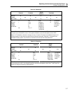
Alarm assignments: Channels 0-3 assigned to outputs 0-3 respectively.
Channels 4-20 assigned to digital I/O lines 4-7, as follows
(appropriate channels are OR’ed to drive each I/O line):
DIGITAL I/O LINE 4 5 6 7
ASSIGNED TO 4 5 6 7
CHANNELS 8 9 10 11
12 13 14 15
16 17 18 19
20
Scan interval time: 0:00:00 (continuous)
Review values (MIN, MAX, LAST): cleared for all channels.
Digital I/O lines: set high (non-alarm)
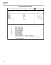
Totalizer: 0, with debounce disabled.
Autoprint: OFF.
Memory Storage (2625A only): OFF, empty
RTD R0 parameter: 100.00 (all channels)
Open Thermocouple Detection (OTC): enabled.
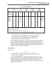
Note
During a scan, a channel set up with autoranging will momentarily slow
the scanning rate whenever the correct range must be determined. This will
occur during the initial scan, with the instrument remembering the range
for subsequent scans. Scans then occur at the normal measurement rate. If
the input signal later changes sufficiently, the scanning rate will again
slow momentarily while the instrument determines the new range.
AC voltage measurements can be made over a wide range of frequencies. The
instrument’s true rms converter insures accuracy for both sine wave and non-sine wave
signals. Refer to Chapter 5 for additional information about true rms measurements.
Resistance measurements can be made to determine either resistance or the value of
another directly related parameter. Slide wire potentiometers, thermistors, and other
sensors with variable resistance outputs are often used to indicate temperature, position,
and other physical parameters. The instrument measures resistance by passing a current