


7–22 433611-001 Service Reference Guide, dx7300
Removal and Replacement Procedures— Slim Tower (ST) Chassis
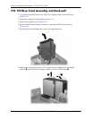
16. Install the serial connector into the new backwall using the two screws that were removed
from the serial connector in a previous step. Reconnect the “Serial A” cable to the system
board.
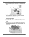
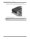
17. Install the system board tray assembly. Be sure the keyhole slot on the system board sits
properly over the locking pins. When the system board is in position, replace the long
mounting screw to secure the system board to the chassis.
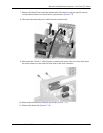
18. Install the chassis fan and connect the control cable to the system board.
19. Reconnect all power and data cables to the system board. Be sure to use proper cable
handling and placement precautions.
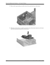
20. Install the power supply. Rotate it to its normal operating position. Be sure to use proper
cable handling and placement precautions.
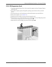
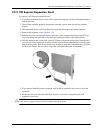
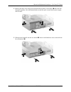
21. Install the full-height PCI expansion card in the available slot in the new PCI riser card cage
assembly.
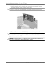
22. Install the new PCI riser card cage assembly on the new backwall by aligning the cage with
the guide rails on the backwall. Press down firmly on the cage to secure it in place on the
backwall. Be sure the riser card in the cage is properly seated in the PCI expansion slot on
the system board.