


Service Reference Guide, dx7300 433611-001 7–35
Removal and Replacement Procedures— Slim Tower (ST) Chassis
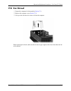
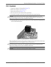
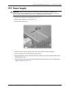
7.14 H e a t s in k
1. Prepare the computer for disassembly (Section 7.1).
2. Remove the computer cover (Section 7.5).
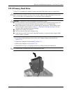
3. Remove the fan shroud (Section 7.12).
4. Disconnect the fan control cable from the system board.
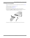
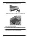
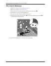
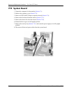
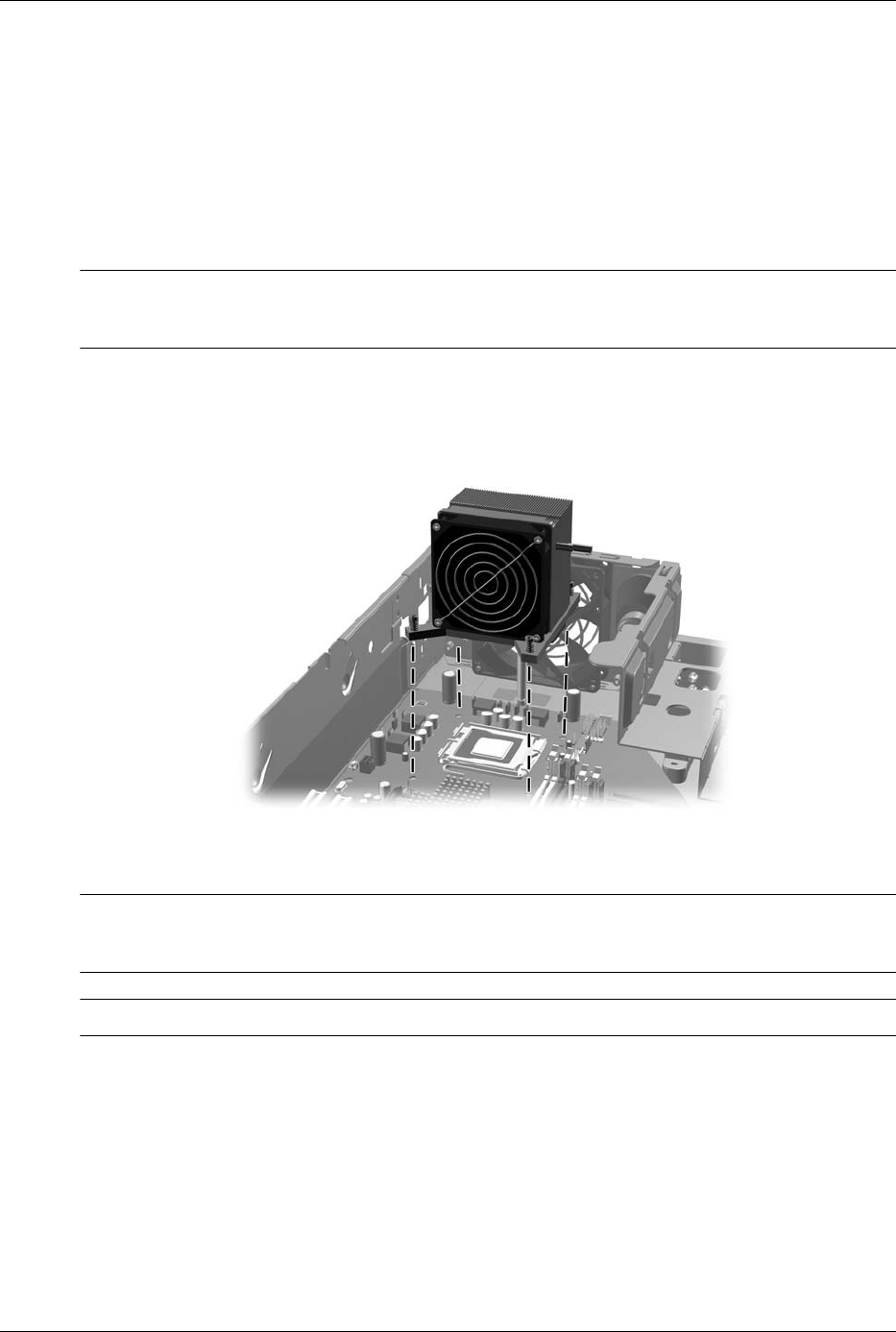
5. Loosen the four captive screws that secure the heatsink to the system board tray.
Ä
CAUTION: Heatsink retaining screws should be removed in diagonally opposite pairs (as in an X) to
even the downward forces on the processor. This is especially important as the pins on the socket are very
fragile and any damage to them may require replacing the system board.
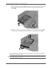
6. Lift the heatsink from atop the processor and set it on its side to keep from contaminating the
work area with thermal grease.
When reinstalling the heatsink, make sure that its bottom has been cleaned with an alcohol wipe
and fresh thermal grease has been applied to the top of the processor.
Ä
CAUTION: Heatsink retaining screws should be tightened in diagonally opposite pairs (as in an X) to
evenly seat the heatsink on the processor. This is especially important as the pins on the socket are very
fragile and any damage to them may require replacing the system board.
Ä
CAUTION: Failure to install the fan shroud may cause the computer to overheat.