


6–10 433611-001 Service Reference Guide, dx7300
Removal and Replacement Procedures— Microtower (MT) Chassis
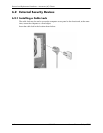
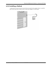
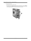
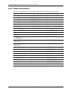
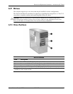
6.6.1 Cable Connections
System board connectors are color-coded to make it easier to find the proper connection.
Cable
To Cable Designator
Power Supply System board, 24-pin P1
Power Supply CPU power, 4-pin P3
Power Supply 1st SATA Hard drive P4
Power Supply 2nd SATA Hard drive P5
Power Supply Diskette drive P8
Power Supply 2nd Optical drive P10
Power Supply 1st Optical drive P11
Cable To PCA Designator
Diskette drive System board P10, FLOPPY (Black)
1st SATA Hard drive System board P60, SATA 0 (Dark Blue)
1st ODD or 2nd Hard drive if
no ODD present
System board P61, SATA 1 (White)
2nd or 4th Hard drive if no
ODD present
System board P62, SATA 2 (Light blue)
2nd ODD or 3rd HDD if no
ODD present
System board P63, SATA 3 (Orange)
Serial port B System board P52, COM B
Hood lock solenoid System board P124, HLCK
Heatsink fan System board P70, CPU FAN
Hood Sensor System board P125, HSENS
Front power button/LED System board P5, F_PNL
Front I/O USB System board P24, FRNT USB (Yellow)
Speaker System board P6, SPKR (White)
Front audio System board P23, FRTNT AUD, (Black)
Chassis fan System board P8, CHASSIS FAN (Red)