


Q2431-90912 Chapter 6 Removing and replacing parts 169
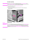
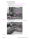
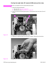
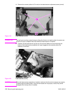
4. Remove one screw (callout 5). Slide the thermistor sensor bar (callout 6) to the right to
release it. Remove the thermistor sensor bar.
Figure 110. Main cooling fan (3 of 4)
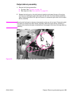
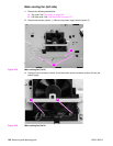
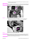
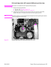
5. Release the two fan-locking tabs (callout 7). Slide the fan out of its mounting bracket.
Figure 111. Main cooling fan (4 of 4)
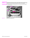
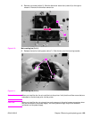
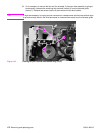
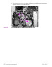
Reinstall note When you install the fan, the air must flow into the printer. Verify that the airflow arrows that are
embossed on the fan body point into the printer.
CAUTION When you install the fan, do not apply too much pressure to the wire-harness connectors when
they are connected to the power supply. Too much pressure might snap off the soldered
connectors on the power supply.
6
7
5
6
87