


Q2431-90912 Chapter 6 Removing and replacing parts 189
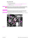
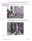
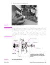
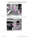
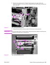
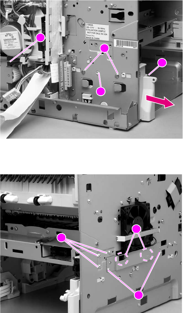
3. Remove two screws (callout 4). Depress the tray 2 right-side guide lock (callout 5) and slide
the guide (callout 6) toward the back of the chassis to release it. Remove the guide. Rotate
the power-switch connector bar (callout 7) away from the printer.
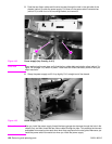
Figure 140. Power supply (2 of 5)
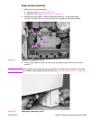
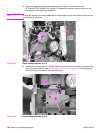
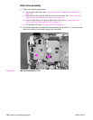
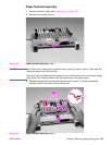
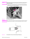
4. Remove five screws (callout 8). Unplug the left-side fan and thermistor sensor connectors on
the power-supply PCA (callout 9; behind the cover plate).
Figure 141. Power supply (left side; 3 of 5)
7
4
5
6
4
5
6
7
7
8
7
8
9
8