


78 Theory of operation Q2431-90912
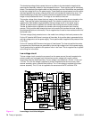
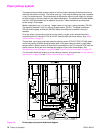
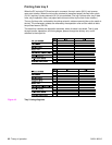
Paper pickup system
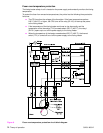
The paper pickup and feed system consists of various kinds of pickup and feed rollers that are
driven by the printer’s motor(s). The printer uses tray 1 (the manual feeding tray) and a cassette
in tray 2 as media sources. The printed media is delivered to either the rear output bin (straight
through printing) or the top output bin (the default destination). Two additional 500-sheet feeders
and one 1,500-sheet feeder can be added to the printer. These accessories are discussed
further along in this chapter.
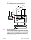
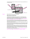
Media is detected in tray 1 by the tray 1 paper sensor (on the tray 1 pickup assembly; PS105).
The media is detected in tray 2 by the tray 2 paper sensor (PS101). The paper size sensor
(PS106) and the paper size switch (SW102) detect the media that is loaded in the tray 2
cassette.
All of the rollers in the printer are driven by two motors, a clutch, and a solenoid which are
controlled by the DC controller PCA (for the HP LaserJet 4300 has three motors). See “Motor
and fan control” on page 70.
The pre-feed, top of page, and fuser assembly delivery sensor (PS102, PS103, PS108) detect
arrival and passing of media along the paper path. If the paper does not reach or pass these
sensors within a specific amount of time the microprocessor on the DC controller PCA halts the
printer functions and a jam error message will appear on the control-panel display. See
“Alphabetical printer messages” on page 258 and “Numerical printer messages” on page 274.
For information about the location of printer switches, sensors, and motors see “Printer switches
and sensors” on page 336 and “Printer motors and fans” on page 337.
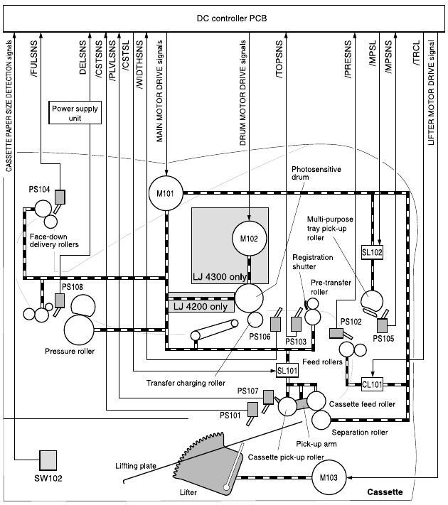
Figure 14. Printer paper pickup and feed block diagram