


HP Omnibook 500 Removal and Replacement 2-1
2
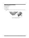
Removal and Replacement
This chapter tells you how to remove and replace the computer’s removable components and
assemblies. The items marked by
•
in the following table are user-replaceable.
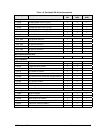
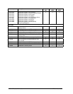
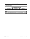
Table 2-1. Removal Cross-Reference
Battery, backup (page 2-34).
Battery, CMOS (page 2-34).
•
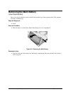
Battery, main (page 2-4).
Cable, hard drive/LED flex (page 2-34).
•
Card, mini-PCI (page 2-14).
Case, bottom (page 2-25).
Case, top (page 2-23).
•
Cover, SDRAM (page 2-17).
•
Covers, display hinge (page 2-17).
•
Covers, display screw (page 2-17).
•
Cover, Trackpoint (page 2-17).
Display assembly (page 2-18).
Doors, docking (page 2-31).
•
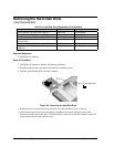
Drive, hard disk (page 2-6).
•
Feet, rubber (page 2-17).
Guide, hard drive (page 2-34).
Heatsink/fan (page 2-21).
•
Keyboard (page 2-10).
•
Module, plug-in (page 2-5).
•
Module, SDRAM (page 2-12).
Panel, audio/PCMCIA (page 2-35).
Panel, mini-PCI (page 2-35).
•
Panel, power button (page 2-9).
PCA, motherboard (page 2-25).
•
PCA, switchboard (page 2-16).
Plate, EMI (page 2-35).
Speaker (page 2-35).
•
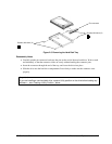
Tray, hard disk drive (page 2-7).
Caution
Always provide proper grounding when performing repairs. Without proper
grounding, an electrostatic discharge can damage the computer or
expansion base and their components.
Notes
Reassembly steps are the reverse of the removal/disassembly steps. Reassembly notes are
included at the end of each removal procedure.
Symbols like this throughout this chapter show approximate full-size screw outlines. You
can use these to verify the sizes of screws before you install them. Installing a wrong-size screw
can damage the unit. (The symbol at the left represents an M2.5×5mm T-head screw.)