


HP Omnibook 500 Removal and Replacement 2-35
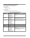
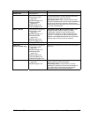
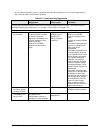
Component Removal Procedure Additional Steps
Heatsink/fan
See page 2-21.
Panel, audio/PCMCIA
Hard disk drive (page 2-6).
Power button panel
(page 2-9).
Keyboard (page 2-10).
Switchboard PCA
(page 2-15).
Display (page 2-18).
Top case (page 2-23).
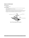
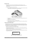
Remove all three screws from the panel. Flip out the
PC Card eject button, so that it stands out from the
side of the unit, then remove the panel.
Reassembly Notes:
Make sure the audio-out jack,
external microphone jack, and PC Card eject button fit
through their openings in the panel. Make sure the
forward screw lug on the panel lies on top of the screw
lug on the hard disk guide.
Panel, mini-PCI
Hard disk drive (page 2-6).
Power button panel
(page 2-9).
Keyboard (page 2-10).
Switchboard PCA
(page 2-15).
Display (page 2-18).
Top case (page 2-23).
Reassembly Notes: Mini-PCI models only.
Route
the panel’s cable (modem models) or cables
(LAN/modem models) to avoid interfering with
installation or operation of other components (see
Figure 2-12 on page 2-15). Make sure the cable or
cables are not trapped beneath the mini-PCI card or
heatsink and do not lay across the heatsink.
PCA, motherboard
See page 2-25.
Plate, EMI
(certain models only)
Hard disk drive (page 2-6).
Power button panel
(page 2-9).
Keyboard (page 2-10).
Switchboard PCA
(page 2-15).
Display (page 2-18).
Top case (page 2-23).
Heatsink/fan (page 2-21).
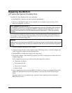
Remove the retaining screw, and lift the EMI plate out
of the unit.
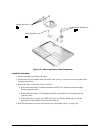
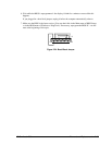
Speaker
Power button panel
(page 2-9).
Keyboard (page 2-10).
Remove both retaining screws, and disconnect the
speaker cable from the motherboard.
Reassembly Notes:
It may be easier to set the
speaker grill in position first, then set the speaker in
place. Be careful not to trap the speaker gasket
beneath the heads of the retaining screws.