


iv
HP Omnibook 500
Replaceable Parts.................................................................................................................4-1
Reference Information......................................................................................................... 5-1
Password Removal Policy .............................................................................................................5-1
Hewlett-Packard Display Quality Statement.................................................................................5-2
Obsolete Parts................................................................................................................................5-4
Figures
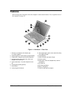
Figure 1-1. Omnibook — Front View..................................................................................................1-3
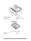
Figure 1-2. Omnibook — Back View ..................................................................................................1-4
Figure 1-3. Omnibook — Bottom View...............................................................................................1-4
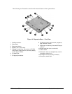
Figure 1-4. Expansion Base — Front View .........................................................................................1-5
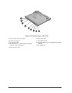
Figure 1-5. Expansion Base — Back View..........................................................................................1-6
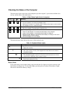
Figure 1-6. Resetting the Computer ...................................................................................................1-10
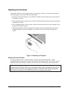
Figure 1-7. Docking the Computer.....................................................................................................1-11
Figure 1-8. Undocking the Computer.................................................................................................1-12
Figure 1-9. Manually Undocking the Computer ................................................................................1-12
Figure 1-10. Connecting a Floppy Disk Drive ...................................................................................1-13
Figure 1-11. Replaceable Component Diagram .................................................................................1-19
Figure 2-1. Disassembly Flow..............................................................................................................2-2
Figure 2-2. Removing the Main Battery...............................................................................................2-4
Figure 2-3. Releasing the Module ........................................................................................................2-5
Figure 2-4. Removing the Hard Disk Drive .........................................................................................2-6
Figure 2-5. Removing the Hard Disk Tray...........................................................................................2-7
Figure 2-6. Removing the Power Button Panel....................................................................................2-9
Figure 2-7. Removing the Keyboard Screws......................................................................................2-10
Figure 2-8. Removing the Keyboard ..................................................................................................2-11
Figure 2-9. Removing the System SDRAM Module..........................................................................2-12
Figure 2-10. Removing an SDRAM Expansion Module ...................................................................2-13
Figure 2-11. Removing the Mini-PCI Card (modem card shown).....................................................2-15
Figure 2-12. Routing the Mini-PCI Cables (LAN/modem card shown) ............................................2-15
Figure 2-13. Removing the Switchboard PCA (wireless model shown)............................................2-16
Figure 2-14. Removing the Display ...................................................................................................2-19
Figure 2-15. Routing the Display Cable.............................................................................................2-19
Figure 2-16. Removing the Heatsink/Fan...........................................................................................2-21
Figure 2-17. Separating the Heatsink and Fan ...................................................................................2-22
Figure 2-18. Removing the Top Case.................................................................................................2-24
Figure 2-19. Removing the Motherboard...........................................................................................2-26
Figure 2-20. Removing Motherboard Components............................................................................2-27
Figure 2-21. Removing Bottom Case Components............................................................................2-30
Figure 2-22. Replacing the Docking Doors........................................................................................2-31
Figure 2-23. Example of Serial Number Label ..................................................................................2-31
Figure 2-24. Boot-Block Jumper........................................................................................................2-33
Figure 3-1. Basic Troubleshooting Steps .............................................................................................3-2
Figure 3-2. e-DiagTools Screens — Basic and Advanced.................................................................3-19
Figure 3-3. Serial and Parallel Loopback Connectors........................................................................3-21
Figure 4-1. Omnibook — Exploded View ...........................................................................................4-2