


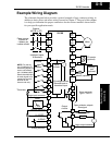
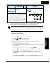
Example Wiring Diagram
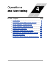
Operations
and Monitoring
4–6
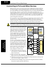
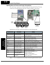
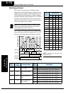
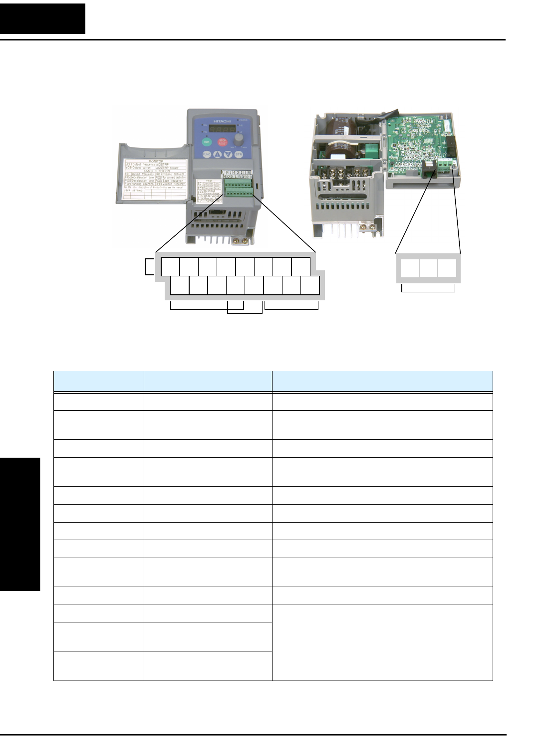
Specifications of Control and Logic Connections
The control logic connectors are located just behind the front panel half-door. The relay
contacts are accessible behind the main door. Connector labeling is shown below.
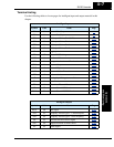
Specifications for the logic connection terminals are in the following table:
Note 1: The two terminals [L] are electrically connected together inside the inverter.
Relay
contacts
Logic
inputs
Analog
inputs
Analog
output
Logic
outputs
12 11
123456L
LH O
OI FM
CM2
P24
AL0
AL2AL1
Terminal Name Description Ratings
[P24] +24V for logic inputs 24VDC, 30 mA max (do not short to terminal L)
[1], [2], [3], [4], [5],
[6]
Discrete logic inputs 27VDC max. (use P24 or an external supply refer-
enced to terminal L)
[L] (top row) *1 GND for logic inputs sum of input 1-6 currents (return)
[11], [12] Discrete logic outputs 50mA maximum ON state current,
27 VDC maximum OFF state voltage
[CM2] GND for logic outputs 100 mA: sum of 11 and 12 currents (return)
[FM] PWM (analog/digital) output 0 to 10VDC, 1 mA, PWM and 50% duty digital
[L] (bottom row) *1 GND for analog inputs sum of OI, O, and H currents (return)
[OI] Analog input, current 4 to 19.6 mA range, 20 mA nominal
[O] Analog input, voltage 0 to 9.6 VDC range, 10VDC nominal,
input impedance 10 kΩ
[H] +10V analog reference 10VDC nominal, 10 mA max
[AL0] Relay common contact 250 VAC, 2.5A (R load) max.,
250 VAC, 0.2A (I load, P.F.=0.4) max.
100 VAC, 10mA min.
30 VDC, 3.0A (R load) max.
30 VDC, 0.7A (I load, P.F.=0.4) max.
5 VDC, 100mA min.
[AL1] Relay contact, normally
closed during RUN
[AL2] Relay contact, normally open
during RUN