


SJ100 Inverter
Operations
and Monitoring
4–41
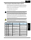
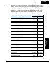
Having two motor profiles lets you store two “personalities” for motors in one inverter’s
memory. The inverter allows the final selection between the two motor types to be made
in the field through the use of an intelligent input terminal function [SET]. This provides
an extra level of flexibility needed in particular situations. See the following table.
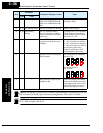
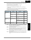
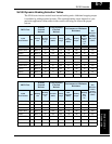
Parameters for the second motor have a function code of the form x2xx. They appear
immediately after the first motor’s parameter in the menu listing order. The following
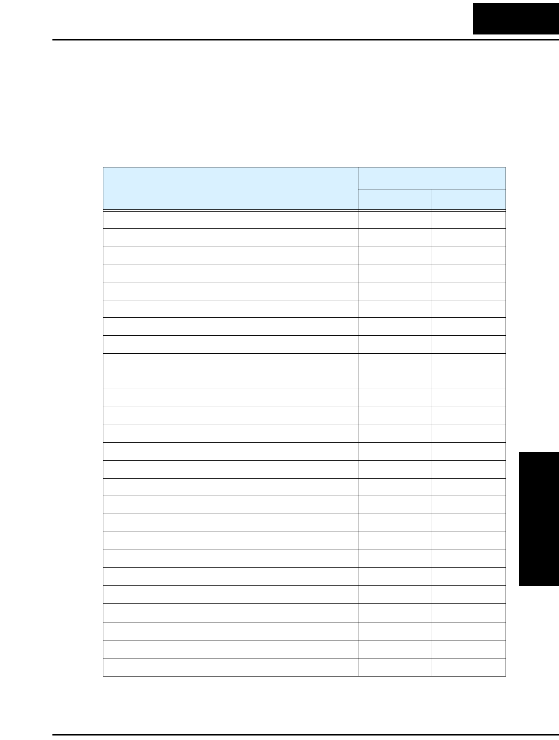
table lists the parameters that have the second parameter register for programming.
Function Name
Parameter Codes
1st motor 2nd motor
Multi-speed frequency setting A_20 A220
Acceleration (1) time setting F_02 F202
Deceleration (1) time setting F_03 F203
Acceleration (2) time setting A_92 A292
Deceleration (2) time setting A_93 A293
Select method to use Acc2/Dec2 A_94 A294
Acc1 to Acc2 frequency transition point A_95 A295
Dec1 to Dec2 frequency transition point A_96 A296
Level of electronic thermal setting B_12 B212
Electronic thermal characteristic B_13 B213
Torque boost method selection A_41 A241
Manual torque boost value A_42 A242
Manual torque boost frequency adjustment A_43 A243
V/f characteristic curve selection A_44 A244
Base frequency setting A_03 A203
Maximum frequency setting A_04 A204
Motor data selection H_02 H202
Motor capacity H_03 H203
Motor poles setting H_04 H204
Motor constant R1 H_20/H_30 H220/H230
Motor constant R2 H_21/H_31 H221/H231
Motor constant L H_22/H_32 H222/H232
Motor constant I
o
H_23/H_33 H223/H233
Motor constant J H_24/H_34 H224/H234
Motor speed constant H_05 H205
Motor stabilization constant H_06 H206