


SJ100 Inverter
Configuring
Drive Parameters
3–25
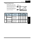
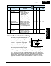
Electronic Thermal Overload Alarm Setting
The thermal overload detection protects the
inverter and motor from overheating due to
an excessive load. It uses a current/inverse
time curve to determine the trip point.
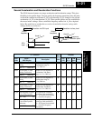
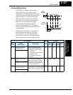
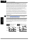
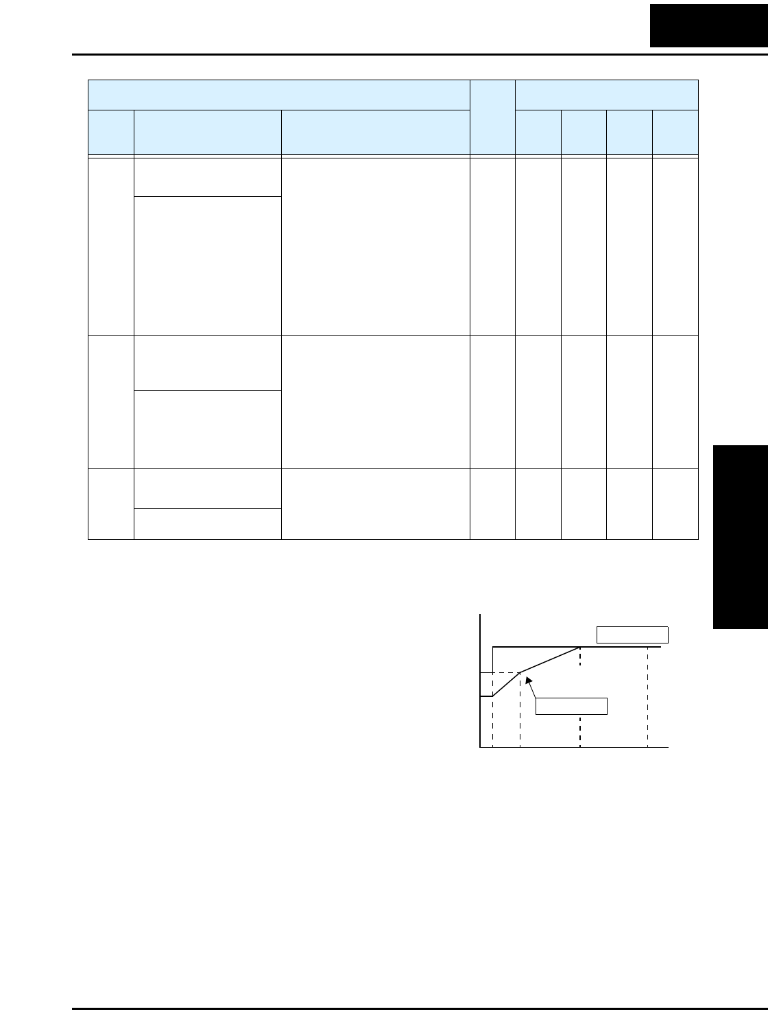
First, use B_13 to select the torque charac-
teristic that matches your load. This allows
the inverter to utilize the best thermal
overload characteristic for your application.
The torque developed in a motor is directly
proportional to the current in the windings,
which is also proportional to the heat generated (and temperature, over time). Therefore,
you must set the thermal overload threshold in terms of current (amperes) for parameter
B_12. The range is 50% to 120% of the rated current for each inverter model. If the
current exceeds the level you specify, the inverter will trip and log an event (error E05) in
the history table. The inverter turns the motor output OFF when tripped. Separate
settings are available for the second motor (if applicable) as shown in the following
table.
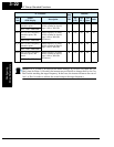
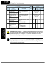
“B” Function
Run
Mode
Edit
Defaults
Func.
Code
Name /
SRW Display
Description
–FE
(CE)
–FU
(UL)
–FR
(Jpn)
Units
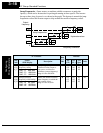
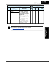
B_01 Selection of automatic
restart mode
Select inverter restart method,
four option codes:
00... Alarm output after trip,
no automatic restart
01... Restart at 0Hz
02... Resume operation after
frequency matching
03... Resume previous freq.
after freq. matching, then
decelerate to stop and display
trip info.
✘ 00 00 00 —
IPS POWR ALM
B_02 Allowable under-
voltage power failure
time
The amount of time a power
input under-voltage can occur
without tripping the power
failure alarm. Range is 0.3 to
25 sec. If under-voltage exists
longer than this time, the
inverter trips, even if the restart
mode is selected.
✘ 1.0 1.0 1.0 sec.
IPS UVTIME 01.0s
B_03 Retry wait time before
motor restart
Time delay after under-voltage
condition goes away, before
the inverter runs motor again.
Range is 0.3 to 100 seconds.
✘ 1.0 1.0 1.0 sec.
IPS WAIT 001.0s
Output frequency
Constant torque
Reduced
torque
B_13
=
01
B_13
=
00
Tor qu e
520 60 120
Hz
100%
80%
60%
0