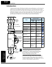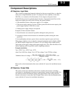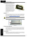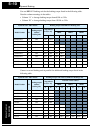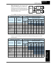
Dynamic Braking
Motor Control
Accessories
5–6
Dynamic Braking Usage Ratio
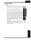
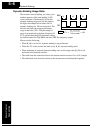
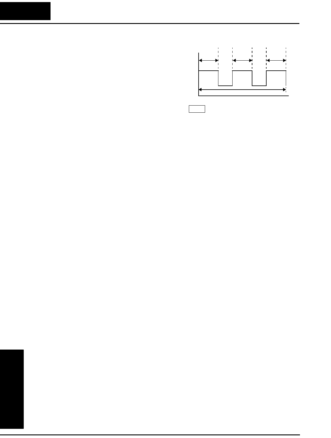
The inverter controls braking via a duty cycle
method (percent of the time braking is ON
versus total time). Parameter B_90 sets the
dynamic braking usage ratio. In the graph to
the right, the example shows three uses of
dynamic braking in a 100-second period. The
inverter calculates the average percentage
usage in that time (T%). The percentage of
usage is proportional to the heat dissipated. If
T% is greater than the B_90 parameter setting,
the inverter enters the Trip Mode and turns OFF the frequency output.
Please note the following:
• When B_90 is set for 0%, dynamic braking is not performed.
• When the T% value exceeds the limit set by B_90, dynamic braking ends.
• When mounting an external dynamic braking unit, set the usage ratio (B_90) to 0.0
and remove the external resistors.
• The cable from the external resistor to the inverter must not exceed 5 m (16 ft.) length.
• The individual wires from the resistor to the inverter must not be bundled together.
BRD
T%
t1 t2 t3++()
100 seconds
-------------------------------
100×=
B90
ON
OFF
t1 t2 t3
t


