


SJ100 Inverter
Motor Control
Accessories
5–9
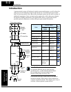
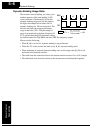
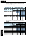
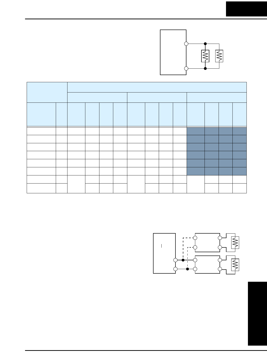
The table below lists 400V-class inverter models
with built-in braking units. Depending on the
desired braking torque or on the inverter model,
the resistor selection specifies multiple resistors
in a parallel or series combination. The example
diagram shows a parallel configuration. Please
refer to the braking resistor documentation for
detailed wiring diagrams.
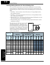
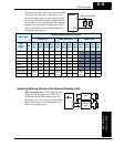
Selecting Braking Resistors for External Braking Units
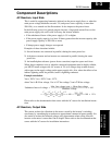
200V Class Inverters – The following tables
specify the braking options for 200V class
SJ100 inverters and the braking torque for
each option. You can connect a single braking
unit to the inverter, or two braking units for
additional stopping torque.
Inverter
JRB x (2) parallel
+
RB
400V Class
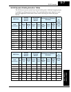
Dynamic Braking Resistor Selection
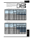
JRB Series SRB/NSRB Series HRB Series
SJ100
Model
Number
HP
Type &
(Qty)
Total
Ohms
Total
Watts
Max.
Duty
Cycle
(%)
Type &
(Qty)
Total
Ohms
Total
Watts
Max.
Duty
Cycle
(%)
Type &
(Qty)
Total
Ohms
Total
Watts
Max.
Duty
Cycle
(%)
004HFE/HFU 1/2 120–1 180 120 2.0 200–1 180 200 4.0
007HFE/HFU 1 120–1 180 120 2.0 200–1 180 200 4.0
015HFE/HFU 2 120–1 180 120 2.0 200–1 180 200 4.0
022HFE/HFU 3 120–2 100 120 1.5 200–2 100 200 3.0
030HFE 4 120–2 100 120 1.5 200–2 100 200 3.0
040HFE/HFU 5 120–2 100 120 1.5 200–2 100 200 3.0
055HFE/HFU 7.5 120–4
x (2) in
series
70 240 1.0 400–1
x (2) in
series
70 800 7.5 RB2
x (2) in
series
70 1200 10.0
075HFE/HFU 10 70 240 1.0 70 800 7.5 70 1200 10.0
Inverter
+
–
Braking
unit
Braking
unit