Auto-tuning for Sensorless Vector Control
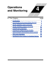
Operations
and Monitoring
4–36
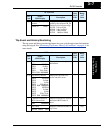
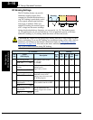
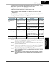
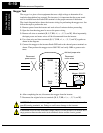
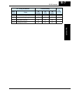
NOTE: During step 11, the motor will make a slight humming sound during the AC and
DC excitation (A and B) steps of the auto-tuning process. This sound is normal.
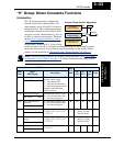
NOTE: When the SLV control method is selected with A_44, set the carrier frequency
to 2.1 kHz or higher with B_83.
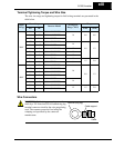
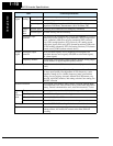
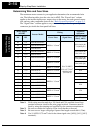
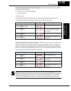
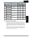
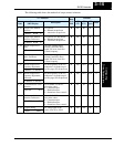
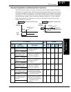
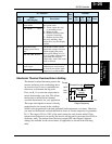
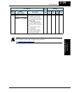
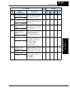
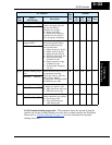
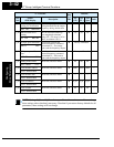
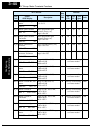
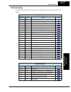
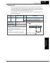
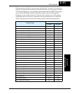
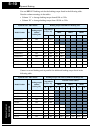
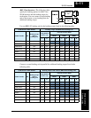
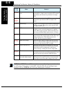
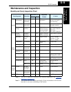
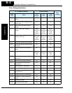
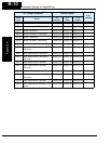
8 A_82 AVR voltage select Select output voltage for motor
200V class: 200/220/230/240
400V class: 380/400/415/440/
460
Voltage setting cannot be greater
than input voltage
9 A_51 DC braking enable Set = 00 to disable DC braking Default = 00 (disabled)
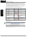
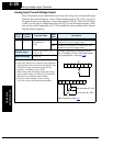
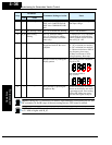
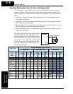
10 H_01 Auto-tuning
Setting
Set = 01 (full auto-tuning
Set = 02 (partial auto-tuning –
measures resistance and induc-
tance only)
Try using H_01 = 01, if possible.
If application or load interferes
with or prohibits motor rotation,
then use H_01 = 02.
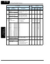
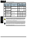
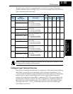
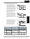
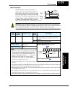
11 — — Press the RUN key on the
keypad and wait for the test to
complete
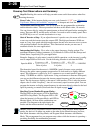
The inverter actions are:
A) .. AC excitation (no rotation)
B)... DC excitation (no rotation)
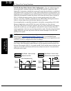
C)... Motor accelerates to 80% of
base frequency, then stops.
D) Motor accelerates to A20
setting frequency, then stops.
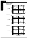
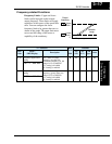
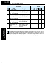
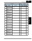
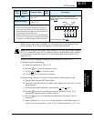
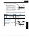
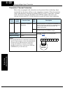
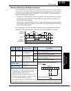
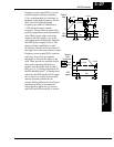
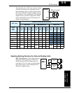
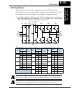
12 — — Interpret results by reading the
display pattern
Auto-tuning process completed
steps A) to D)
Auto-tuning failed at
step A) or B)
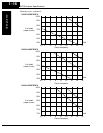
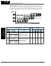
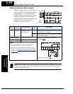
13 — — Reset Inverter by pressing the
Stop/Reset Key
Inverter will display alternating
pattern on the display and return
to parameter menu. Auto-tuning
will be OFF. Make any correc-
tions and start again at step 10.
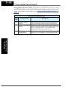
Step
Parameter
Parameter Setting or Action Notes
Code Name