


Analog and Digital Monitor Output
Operations
and Monitoring
4–34
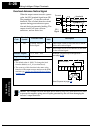
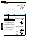
TIP: When using the analog meter for monitoring, adjust the meter so it has a zero
reading when the [FM] output is zero. Then use scale factor B_81 to adjust the [FM]
output so the maximum frequency in the inverter corresponds to a full-scale reading on
the meter.
The following accuracy notes apply for PWM monitor outputs:
• The monitor accuracy for frequency monitoring after adjustment is about ±5%.
Depending on the motor, the accuracy may exceed this value.
• The monitor display accuracy for current (normally ± 20%, depending on the
connected motor’s characteristics) can be improved by adjusting parameter B_32.
• The accuracy of the current reading is given by the equation:
• If precise current measurement is necessary, use the moving-coil type ammeter
between the inverter and the motor.
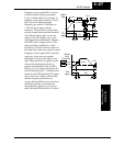
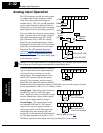
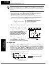
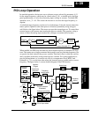
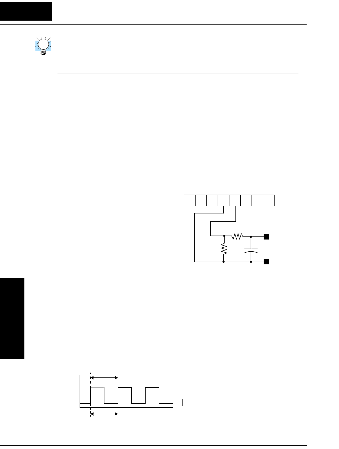
PWM Smoothing Circuit – You may also
wish to smooth the PWM signal at the [FM]
terminal and convert it to an analog signal.
The [FM] terminal will then generate a
relatively stable DC analog voltage that
represents the output value. To do this, use
the circuit shown to the right. Note the
output impedance of the circuit is at least
82kΩ, so the monitoring device needs an
input impedance of 1MΩ or greater. Other-
wise, the impedance of the smoothing
circuit will cause a non-linearity in the reading.
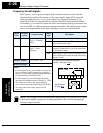
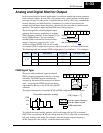
FM Signal Type
The frequency-modulated output at terminal [FM] varies its frequency with the inverter
output frequency (C_23=02). The multiplier is 10, such that the maximum [FM] signal
frequency is 10 x 360 = 3.6 kHz, or 10 times the inverter’s maximum output frequency.
The signal at [FM] uses the parameter A_04 Maximum frequency setting. For example, if
A_04 = 60 Hz, then the maximum signal value at [FM] will be 10 x 60 = 600 Hz. This
frequency is digitally controlled for accuracy, and does not use the B_81 gain setting
when C_23=02 (frequency modulation selection).
Imc Im–
Ir
----------------------
100× 20%±≤
Im = Inverter output current (measured)
Imc = Monitor display current
Ir = Inverter rated current
+
12 11LH O
OI FM
CM2
33kΩ
82kΩ
1µF
Volts
–
–
+
+
See I/O specs on page 4–6.
T
1
[FM] Output value 10×
---------------------------------------------------------=
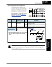
Selects FM type output
[FM]
C_23
=
02
50% fixed duty cycle
10V
0V
t
T
[FM] Output value
1
T10×
---------------=