


SJ100 Inverter
Operations
and Monitoring
4–33
Analog and Digital Monitor Output
In the system design for inverter applications it is useful to monitor the inverter operation
from a remote location. In some cases, this requires only a panel-mounted analog meter
(moving-coil type). In other cases, a controller device such as a PLC may command the
inverter frequency and other functions. Sometimes it is useful to have the inverter
transmit the (real-time) output frequency value back to the controller to confirm actual
operation. The monitor output function [FM] serves these purposes.
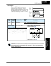
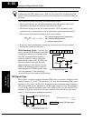
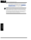
The inverter provides an analog/digital output
primarily for frequency monitoring on terminal
[FM] (frequency monitor). It uses terminal [L] as
analog GND reference. You can configure
terminal [FM] to transmit the inverter current
output or frequency output in pulse-width
modulated format (PWM). You can also config-
ure terminal [FM] to output the frequency value in a frequency-modulated (FM) format.
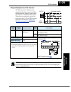
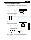
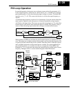
The following table lists terminal [FM] configurations. Use function C_23 to configure.
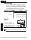
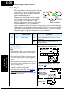
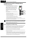
PWM Signal Type
The pulse-width modulated signal at terminal
[FM] is primarily designed for driving a moving-
coil meter. The PWM signal is automatically
averaged by the inertia of the moving-coil mecha-
nism—converting the PWM signal to an analog
representation. Be sure to use a 10V full-scale DC
voltmeter.
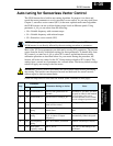
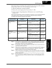
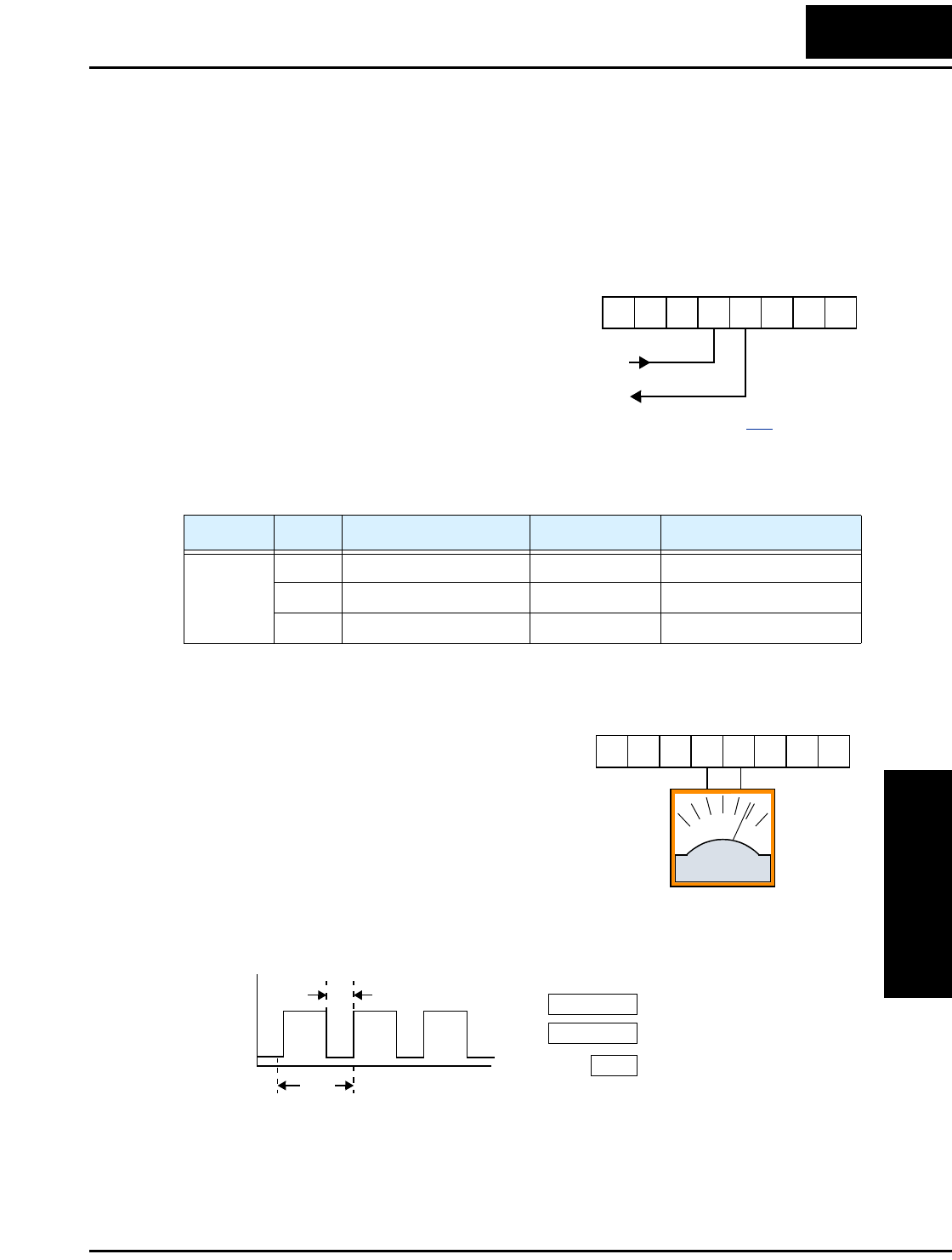
The signal characteristics of terminal [FM] in PWM configuration is shown below:
To calibrate the meter reading, generate a full-scale output (always ON) at terminal
[FM]. Then use parameter B_81(gain setting from 0 to 255) to adjust the corresponding
full-scale reading of the meter. For example, when the inverter output frequency is
60 Hz, change the value of B_81 so that the meter reads 60 Hz.
Func. Code Description Waveform Full Scale value
C_23
00 Output frequency PWM 0 – Max. frequency (Hz)
01 Output current PWM 0 – 200%
02 Output frequency FM 0 – Max. frequency (Hz)
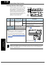
A GND
Analog/digital Output
12 11LH O
OI FM
CM2
See I/O specs on page 4–6.
0 to 10V,
1 mA
12 11LH O
OI FM
CM2
–+
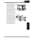
Inverter output current
[FM]
Inverter output frequency
Pulse-width modulation (analog)
PWM scale factor
C_23
=
00
C_23 = 01
B81
10V
0V
TT = 4 ms
t
[FM] Output
t
T
---=
t