


Using Intelligent Input Terminals
Operations
and Monitoring
4–8
Using Intelligent Input Terminals
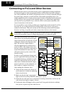
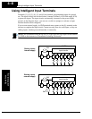
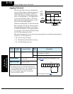
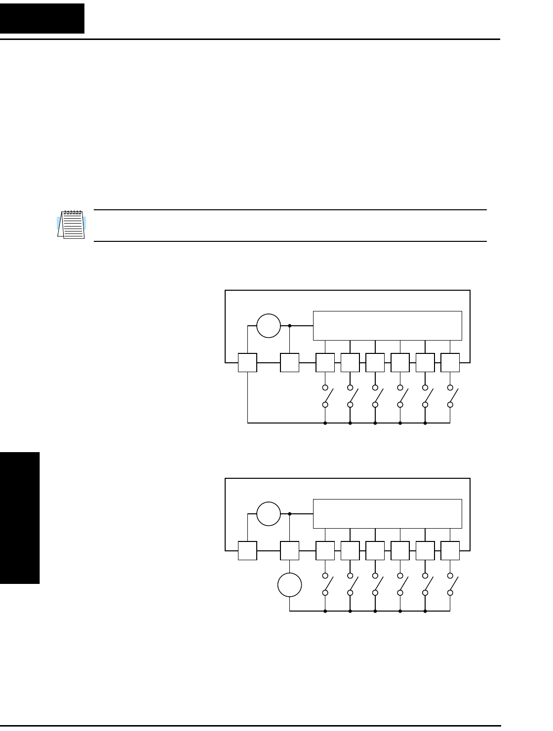
Terminals [1], [2], [3], [4], [5], and [6] are identical, programmable inputs for general
use. The input circuits can use the inverter’s internal (isolated) +24V field supply (P24)
to power the inputs. The input circuits are internally connected to the power supply
ground. As the diagram shows, you can use a switch (or jumper) to activate an input
terminal that has been configured.
If you use an external supply, its GND terminal must connect to the [L] terminal on the
inverter to complete the input circuit. Current can only flow into each input, so they are
sinking inputs, whether powered internally or externally.
NOTE: We recommend using the top row [L] logic GND for logic input circuits and the
[L] GND on the bottom row of terminals for analog I/O circuits.
.
SJ100 Inverter
Input circuits
123456L
P24
+ –
24V
Sinking inputs,
internal supply
SJ100 Inverter
Input circuits
123456L
P24
+ –
24V
Sinking inputs,
external supply
–
+
24V