


SJ100 Inverter
Operations
and Monitoring
4–25
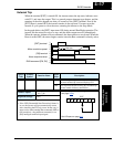
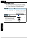
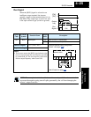
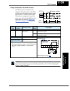
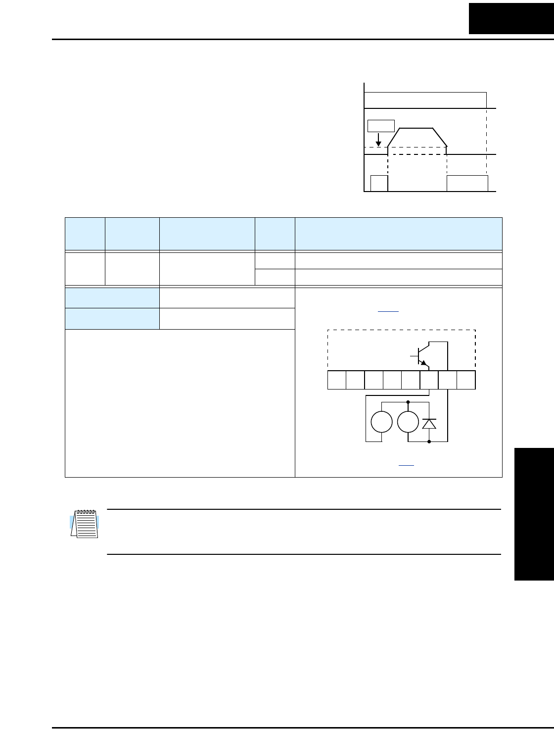
Run Signal
When the [RUN] signal is selected as an
intelligent output terminal, the inverter
outputs a signal on that terminal when it is in
Run Mode. The output logic is active low, and
is the open collector type (switch to ground).
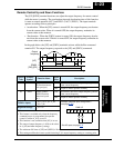
NOTE: The example circuit in the table above drives a relay coil. Note the use of a diode
to prevent the negative-going turn-off spike generated by the coil from damaging the
inverter’s output transistor.
[FW],
[RV]
Output
freq.
Run
Signal
start freq.
B82
t
ON
1
0
1
0
Option
Code
Terminal
Symbol
Function Name
Output
State
Description
00 RUN Run Signal ON when inverter is in Run Mode
OFF when inverter is in Stop Mode
Valid for outputs:
11, 12, AL0 – AL2
Required settings:
(none)
Notes:
•
The inverter outputs the [RUN] signal whenever the
inverter output exceeds the start frequency specified
by parameter B_82. The start frequency is the initial
inverter output frequency when it turns ON.
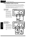
RY
+
–
12 11LH O
OI FM
CM2
Example (default output configuration
shown—see page 3–38
):
Inverter output
terminal circuit
See I/O specs on page 4–6
.
RUN