


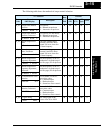

“A” Group: Standard Functions
Configuring
Drive Parameters
3–10
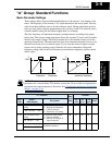
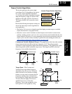
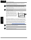
Analog Input Settings
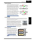
The inverter has the capability to accept an external analog input that can command the
output frequency to the motor. Voltage input (0 –10V) and current input (4–20mA) are
available on separate terminals ([O] and [OI], respectively). Terminal [L] serves as
signal ground for the two analog inputs. The analog input settings adjust the curve
characteristics between the analog input and the frequency output.
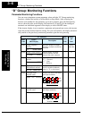
In the graph below (left), A_13 and A_14 select the active portion of the input voltage or
current range. The parameters A_11 and A_12 select the start and end frequency of the
converted output frequency range, respectively. Together, these four parameters define a
line segment as shown (below, right). When the line does not begin at the origin, A_15
defines whether the inverter outputs 0Hz or the A_11 frequency when the analog input
value is less than the A_13 setting (determines the non-linear part of the translation).
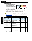
A203 Base frequency setting,
2nd motor
Settable from 50 Hz to the
maximum frequency
✘ 50.0 60.0 60.0 Hz
2F-BASE 060Hz
A_04 Maximum frequency
setting
Settable from the base
frequency up to 360 Hz
✘ 50.0 60.0 60.0 Hz
F-MAX 060Hz
A204 Maximum frequency
setting, 2nd motor
Settable from the base
frequency up to 360 Hz
✘ 50.0 60.0 60.0 Hz
2F-MAX 060Hz
“A” Function
Run
Mode
Edit
Defaults
Func.
Code
Name /
SRW Display
Description
–FE
(CE)
–FU
(UL)
–FR
(Jpn)
Units
A12
A11
A13 A14
A12
A11
A_15
=
00
A_15
=
01
A13 A14
Frequency Frequency
0V
4mA
10V
20mA
% Input scale % Input scale
0V
4mA
10V
20mA
00
%
%