


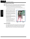
Using the Front Panel Keypad
Inverter Mounting
and Installation
2–22
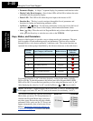
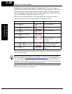
• Parameter Display - A 4-digit, 7-segment display for parameters and function codes.
• Display Units, Hertz/Amperes - One of these LEDs will be ON to indicate the units
associated with the parameter display.
• Power LED - This LED is ON when the power input to the inverter is ON.
• Function Key - This key is used to navigate through the lists of parameters and
functions for setting and monitoring parameter values.
• Up/Down ( , ) Keys - Use these keys alternately to move up or down the lists of
parameter and functions shown in the display, and increment/decrement values.
• Store ( ) Key - When the unit is in Program Mode and you have edited a parameter
value, press the Store key to write the new value to the EEPROM.
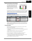
Keys, Modes, and Parameters
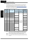
Purpose of the keypad is to provide a way to change modes and parameters. The term
function applies to both monitoring modes and parameters. These are all accessible
through function codes that are primarily 3-character codes. The various functions are
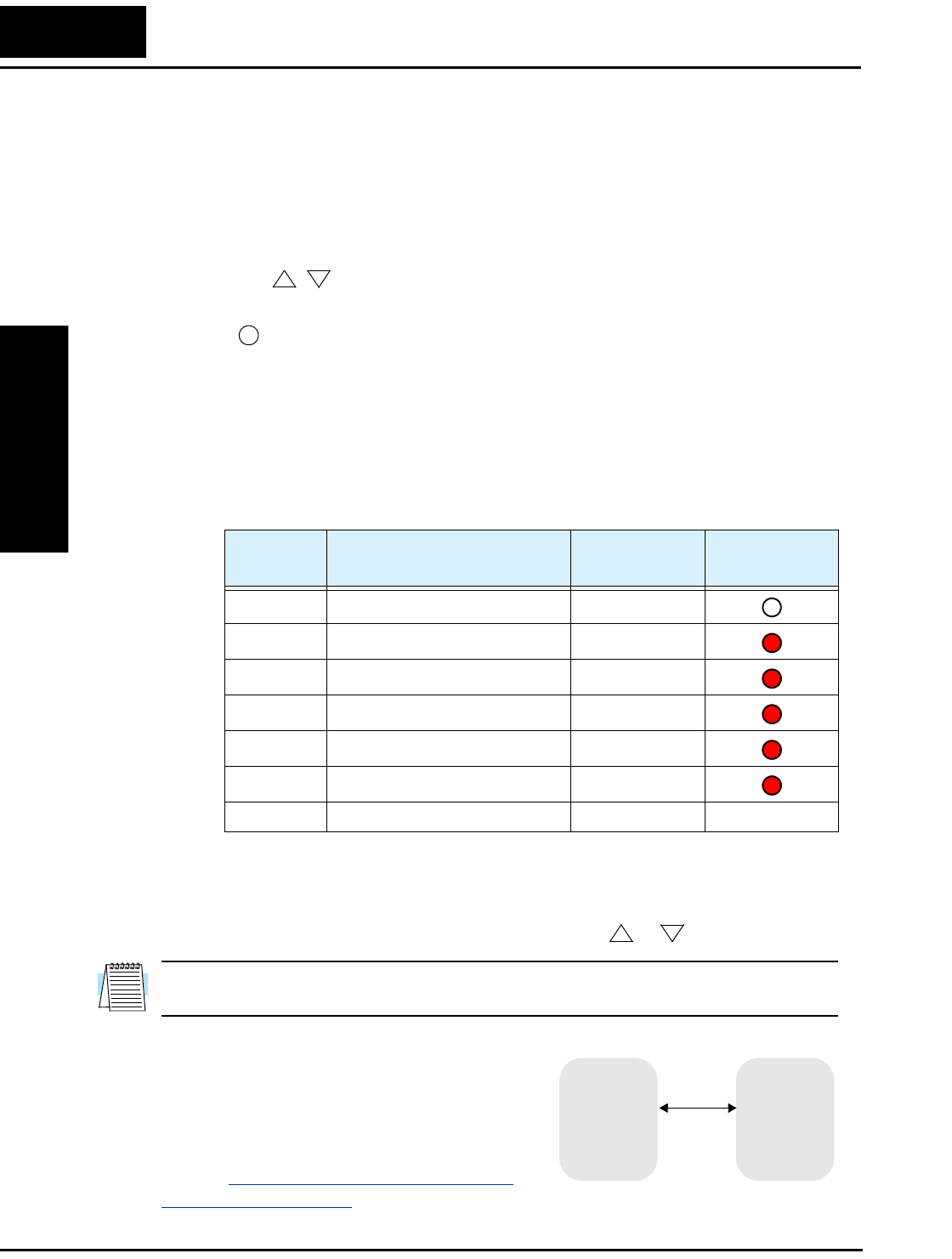
separated into related groups identifiable by the left-most character, as the table shows.
For example, function “A_04” is the base frequency setting for the motor, typically
50 Hz or 60 Hz. To edit the parameter, the inverter must be in Program Mode (PGM
LED will be ON). You use the front panel keys to first select the function code “A_04.”
After displaying the value for “A_04,” use the Up/Down ( or ) keys to edit it.
NOTE: The inverter 7-segment display shows lower case “b” and “d,” meaning the same
as the upper case letters “B” and “D” used in this manual (for uniformity “A to F”).
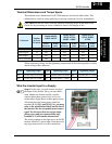
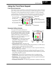
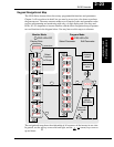
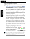
The inverter automatically switches into Monitor
Mode when you access “D” Group functions. It
switches into Program Mode when you access
any other group, because they all have editable
parameters. Error codes use the “E” Group, and
appear automatically when a fault event occurs.
Refer to “
Monitoring Trip Events, History, &
Conditions” on page 6–5 for error code details.
1
2
STR
Function
Group
Type (Category) of Function Mode to Access
PGM LED
Indicator
“D” Monitoring functions Monitor
“F” Main profile parameters Program
“A” Standard functions Program
“B” Fine tuning functions Program
“C” Intelligent terminal functions Program
“H” Motor constant functions Program
“E” Error codes — —
1
2
“D” Group
MONITOR PROGRAM
“A” Group
“B” Group
“C” Group
“F” Group
“H” Group
“D” Group