


Control Logic Signal Specifications
Operations
and Monitoring
4–6
Control Logic Signal Specifications
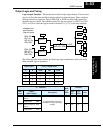
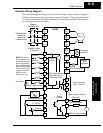
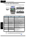
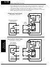
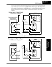
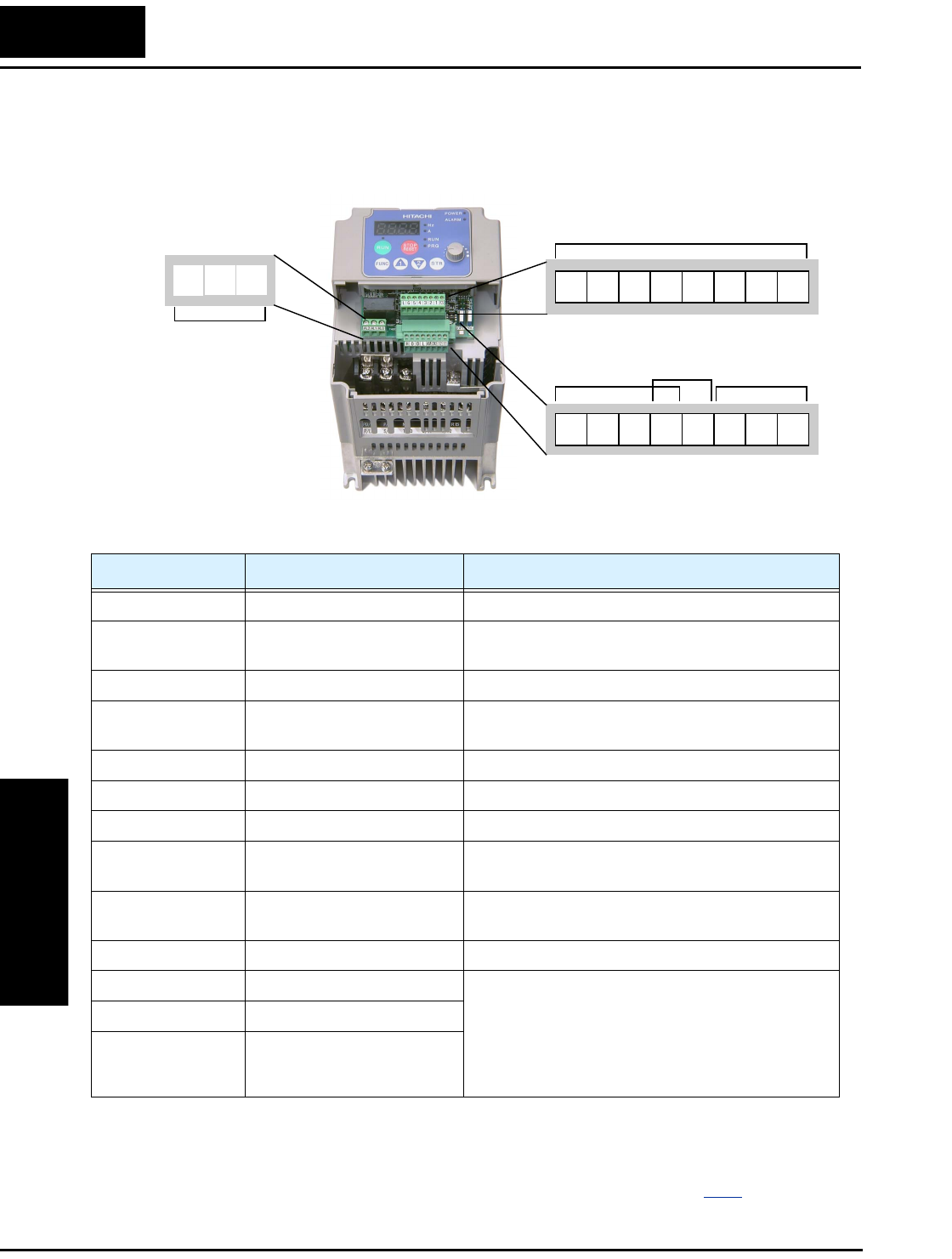
The control logic connectors are located just behind the front housing cover. The relay
contacts are just to the left of the logic connectors. Connector labeling is shown below.
Specifications for the logic connection terminals are in the following table:
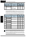
Note 1: The two terminals [L] are electrically connected together inside the inverter.
Note 2: We recommend using the top row [L] logic GND for logic input circuits and
the [L] GND on the bottom row of terminals for analog I/O circuits.
Note 3: Default relay N.O./N.C. configuration is reversed. See page 4–35
.
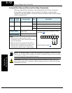
Relay
contacts
Logic inputs
Analog
inputs
Analog
output
Logic
outputs
12 11
123456L
LH O
OI AM
CM2
PCS
AL2
AL0AL1
Terminal Name Description Ratings
[PCS] +24V for logic inputs 24VDC, 30 mA max. (do not short to terminal L)
[1], [2], [3], [4], [5],
[6]
Discrete logic inputs 27VDC max. (use PCS or an external supply refer-
enced to terminal L)
[L] (top row) *1 GND for logic inputs sum of input [1]—[6] currents (return)
[11], [12] Discrete logic outputs 50mA maximum ON state current,
27 VDC maximum OFF state voltage
[CM2] GND for logic outputs 100 mA: sum of 11 and 12 currents (return)
[AM] Analog voltage output 0 to 10VDC, 1mA maximum
[L] (bottom row) *2 GND for analog signals sum of OI, O, H, and AM currents (return)
[OI] Analog input, current 4 to 19.6 mA range, 20 mA nominal,
input impedance 250 Ω
[O] Analog input, voltage 0 to 9.8 VDC range, 10VDC nominal,
input impedance 10 kΩ
[H] +10V analog reference 10VDC nominal, 10 mA max
[AL0] Relay common contact 250 VAC, 2.5A (R load) max.,
250 VAC, 0.2A (I load, P.F.=0.4) max.
100 VAC, 10mA min.
30 VDC, 3.0A (R load) max.
30 VDC, 0.7A (I load, P.F.=0.4) max.
5 VDC, 100mA min.
[AL1] *3 Relay contact, normally open
[AL2] *3 Relay contact, normally
closed