


SJ200 Inverter
Inverter Mounting
and Installation
2–5
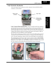
Logic Connector Introduction
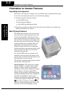
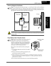
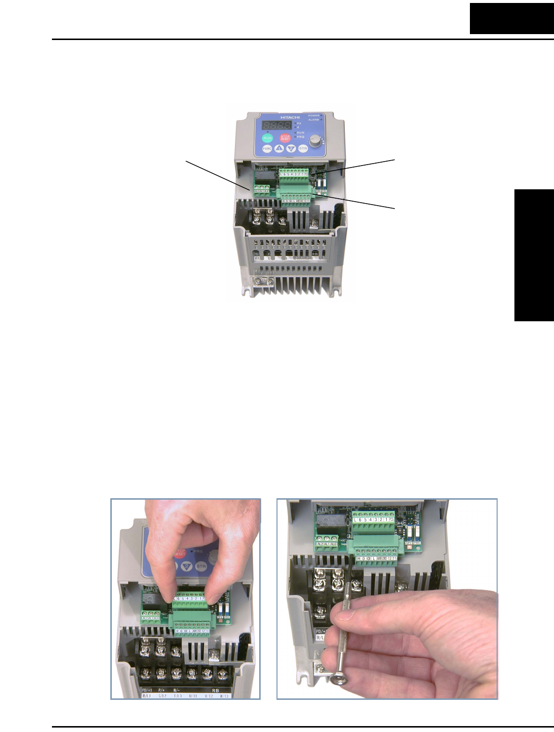
After removing the front housing cover, take a moment to become familiar with the
connectors, as shown below.
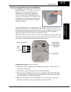
Logic Connector Removal/Replacement - The two 8-position main logic connectors
are removable from the circuit board to make testing or service more convenient. Note
that the relay output connector is not removable, as it must carry higher currents and
provide high integrity for alarm conditions. The alarm circuit may carry hazardous live
voltages (from external wiring) even when the main power to the inverter is OFF. So,
never directly touch any terminal or circuit component.
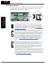
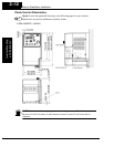
The logic input connector (top connector) can be removed by pulling gently upward as
shown (below left). DO NOT force the connector, as damage to the circuit board may
occur. Try gently shifting the connector side-to-side while pulling, if having difficulty.
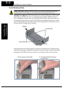
The analog input/output and logic output connector (bottom connector) has retention
screws. DO NOT attempt to remove the connector before loosening the screws. As the
figure shows (below right), use a small Phillips screwdriver to loosen the screw at each
end. The connector can be pulled forward easily after the screws are removed.
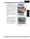
Analog input/
output and logic
outputs
Relay output
contacts
Logic inputs