SJ200 Inverter
Appendix B
B–37
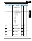
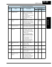
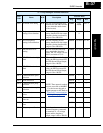
C041 Overload level setting R/W Sets the overload signal level
between 0% and 200% (from 0
to two times the rated current
of the inverter)
00BBh 0 to
20000
0.01 %
C042 Frequency arrival
setting for acceleration
R/W Sets the frequency arrival
setting threshold for the output
frequency during acceleration,
range is 0.0 to 400.0 Hz
00BCh 0 to 4000
*1
0.1 Hz
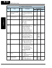
C043 Arrival frequency
setting for deceleration
R/W Sets the frequency arrival
setting threshold for the output
frequency during deceleration,
range is 0.0 to 400.0 Hz
00BDh 0 to 4000 0.1 Hz
C044 PID deviation level
setting
R/W Sets the allowable PID loop
error magnitude (absolute
value), SP - PV, range is 0.0 to
100%, resolution is 0.1%
00BEh 0 to 1000 0.1 %
C052 PID FBV function high
limit
R/W When the PV exceeds this
value, the PID loop turns OFF
the PID Second Stage Output,
range is 0.0 to 100.0%
00EAh 0 to 1000 0.1 %
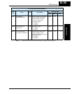
C053 PID FBV function low
limit
R/W When the PV goes below this
value, the PID loop turns ON
the PID Second Stage Output,
range is 0.0 to 100.0%
00EBh 0 to 1000 0.1 %
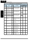
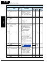
C071 Communication speed
selection
—
NOTE: These network settings
are not accessible to ModBus.
Use the inverter keypad or
digital operator to edit. Refer to
“Network Communication
Settings” on page 3–50.
00C0h — —
C072 Node allocation — 00C1h — —
C074 Communication parity
selection
— 00C3h — —
C075 Communication stop bit
selection
— 00C4h — —
C076 Communication error
select
— 00ECh — —
C077 Communication error
time-out
—00EDh——
C078 Communication wait
time
— 00C5h — —
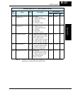
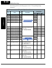
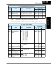
C081 O input span calibration R/W Scale factor between the
external frequency command
on terminals L – O (voltage
input) and the frequency
output, range is 0.0 to 200.0%
00C7h 0 to 2000 0.1 %
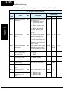
“C” Group Intelligent Terminal Functions
Func.
Code
Name R/W Description
Network Data
Reg. Range Res.


