


10 IBM ^ xSeries 440 Planning and Installation Guide
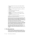
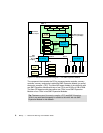
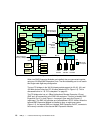
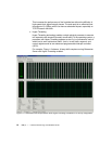
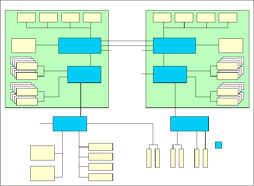
Figure 1-5 xSeries 440 system block diagram — two SMP Expansion Modules
When two SMP Expansion Modules are installed, they are connected together
using two 3.2 GBps SMP Expansion Ports. The third scalability port is not used in
this single-node eight-way configuration.
The two PCI bridges in the XA-32 chipset provide support for 33, 66, 100, and
133 MHz devices using four PCI-X buses (labeled A-D in Figure 1-5). This is
discussed further in 1.8, “PCI subsystem” on page 23.
The PCI bridge also has a 1 GBps bi-directional Remote Expansion I/O port
(RXE port) for connectivity to the RXE-100 enclosure. This port is labeled “RXE
Expansion Port A” in both Figure 1-4 on page 8 (four-way) and Figure 1-5
(eight-way). The RXE-100 provides up to an additional 12 PCI-X slots. When the
second SMP Expansion Module is installed to form an eight-way system
(Figure 1-5), the second RXE port, labeled “RXE Expansion Port B”, connects to
the memory controller of the second SMP Expansion Module.
CEC 2
CEC 1
SMP Expansion
Ports (3.2GBps)
Ultra160
SCSI
Gigabit
Ethernet
Video
USB
Kbd/Ms
RSA
33 MHz66 MHz
64-bit
66 MHz
64-bit
100 MHz
64-bit
133 MHz
Bus A66 MHz
PCI bridge
RXE Expansion
Port A (1 GBps)
B-100
D-133C-133
PCI bridge
IBM XA-32
core chipset
RXE
Expansion
Port B
(1 GBps)
SDRAM
3.2 GBps
32 MB
L4 cache
CPU 1 CPU 2 CPU 3 CPU 4
400 MHz
SDRAM
3.2 GBps
3.2 GBps
Processor &
cache controller
2 GBps
Memory
controller
3.2 GBps
3.2
GBps
SDRAM
SDRAM
100 MHz
SDRAM
3.2 GBps
32 MB
L4 cache
CPU 1CPU 2CPU 3CPU 4
400 MHz
SDRAM
3.2 GBps
3.2 GBps
Processor &
cache controller
2 GBps
Memory
controller
3.2 GBps
3.2
GBps
SDRAM
SDRAM
100 MHz