


18 CMX158886 cpuModule BDM-610000049 Rev G
Connector Locations
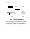
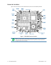
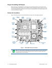
Figure 3 shows the connectors and the ATA/IDE Disk Chip socket of the CMX158886 cpuModule.
Figure 3 CMX158886 Connector Locations
Note Pin 1 of each connector is indicated by a white silk-screened square on the top side of the board
and a square solder pad on the bottom side of the board. Pin 1 of the bus connectors match when
stacking PC104-Plus or PCI-104 modules.
ATA/ IDE
Disk Chip
(U16)
PCI Bus (CN16)
COM1
(CN7)
COM2
(CN8)
SVGA
Video
(CN18)
EIDE (CN10)
Auxiliary Power
(CN3)
Multi-
Function
(CN5)
multiPort
(CN6)
LVDS Flat
Panel
(CN19)
Ethernet
(CN20)
USB 2.0
(CN17)
Audio
(CN11)
ISA Bridge Link
(CN4)
Cont. Fan
(CN14)
Power
Mngmt.
(CN12)
Switched
Fan
(CN15)
Battery
(CN13)