


BDM-610000049 Rev G Chapter 3: Connecting the cpuModule 51
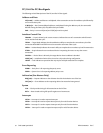
Power Supplies and VIO
+5 V — +5 V supply connected to the PC/104 bus and Auxiliary Power Connector (CN3) +5 V supplies. This
is the only power supply that is required for board operation.
+12 V — +12 V supply connected to the PC/104 bus and Auxiliary Power Connector (CN3) +12 V supplies.
–12 V — –12 V supply connected to the PC/104 bus and Auxiliary Power Connector (CN3) –12 V supplies.
+3.3 V — The +3.3 V pins on the PC/104-Plus (PCI) connector are connected to the Auxiliary Power
Connector (CN3) by default. To supply +3.3V via the onboard +3.3V power supply, contact RTD Technical
Support.
VIO — This signal is typically the I/O power to the bus drivers on a PCI bus card, or used by the clamp diodes
on a PCI bus card. This is always driven by the cpuModule. By default, the signaling level is set to +3.3 V. For
information on configuring VIO for +5 V, contact RTD Technical Support.
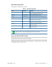
ATX Power Management Signals (optional)
If an ATX power supply is connected to the system, the following signals listed below may be used to wake the
system from low power modes. For more information on these signals, refer to the Power Management section
on page 73.
+5V_STDBY — Some low power modes require that +5 V standby power is applied to the cpuModule
during the wake event. This signal is an input to the CPU.
PME# — Power Management Event input
PSON# — This is an active low open-drain output used to turn the power supply on when the system is
exiting a low power state.
Note Use of these signals will require board customization. For more information, contact the RTD.