


86 CMX158886 cpuModule BDM-610000049 Rev G
Jumper Settings and Locations
Many cpuModule options are configured by positioning jumpers. Jumpers are labeled on the board as JP
followed by a number.
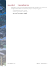
Some jumpers have three pins, allowing three settings:
• Pins 1 and 2 connected (indicated as “1–2”)
• Pins 2 and 3 connected (indicated as “2–3”)
• No pins connected
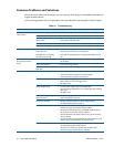
Some jumpers have two pins, allowing two settings:
• Pins 1 and 2 connected (indicated as “closed”)
• Pins 1 and 2 unconnected (indicated as “open”)
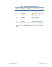
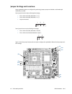
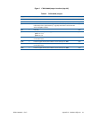
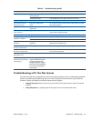
Figure 7 shows the jumper locations that are used to configure the cpuModule. Table 62 lists the jumpers and
their settings.
1
2
3
1
2
JP9
JP2
JP13
JP6
JP14
JP5
JP1
JP12
JP11