


BDM-610000049 Rev G Chapter 2: Getting Started 19
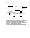
Power is normally supplied to the cpuModule through the PCI bus connectors (CN16). If you are placing the
cpuModule onto a PC/104-Plus or PCI-104 stack that has a power supply, you do not need to make additional
connections to supply power.
If you are using the cpuModule without a PCI-104 or PC/104-Plus stack or with a stack that does not include a
power supply, refer to Auxiliary Power (CN3) on page 26 for more details.
Some PCI-104 and PC/104-Plus expansion cards may require +3.3V supplied on the PC/104-Plus (PCI) connector
(CN16). To learn how to supply this voltage, refer to Auxiliary Power (CN3) on page 26 and Jumper Settings and
Locations on page 86.
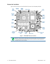
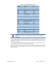
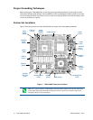
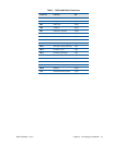
Table 5 CMX158886 Basic Connectors
Connector Function Size
CN3 Auxiliary Power 12-pin
CN4 Bridge Link 4-pin
CN5 Utility Port 10-pin
CN6 multiPort 26-pin
CN7 Serial Port 1 (COM1) 10-pin
CN8 Serial Port 2 (COM2) 10-pin
CN10 EIDE Connector 44-pin
CN11 Audio Connector 10-pin
CN12 External Power Management 3-pin
CN13 RTC Battery Input (optional) 2-pin
CN14 Fan Power (+5V) 2-pin
CN15 Fan Power (switched) 2-pin
CN16 PC/104-Plus (PCI) Bus 120-pin
CN17 USB 2.0 10-pin
CN18 Video (SVGA) 10-pin
CN19 Flat Panel Video (LVDS) 30-pin
CN20 Ethernet 10-pin
U16 ATA/IDE Disk Chip Socket 32-pin
WARNING If you connect power incorrectly, the module will almost certainly be damaged or destroyed.
Such damage is not covered by the RTD warranty! Please verify connections to the module before
applying power.