


BDM-610000049 Rev G Chapter 4: Using the cpuModule 69
Real Time Clock Control
Overview
The cpuModule is equipped with a Real Time Clock (RTC) which provides system date and time functions.
When the cpuModule is turned off, a battery must be attached to the utility connector to provide power to the
RTC. Without power, the RTC will lose the date/time information when the system is turned off.
The RTC also provides an “alarm” function. This may be used to generate an interrupt at a particular time and
day. This feature is commonly used to wake up the system from Sleep/Standby to run a scheduled task
(defragment the hard drive, back up files, etc.).
In addition to the date/time/alarm functions, the RTC contains several bytes of battery-backed RAM, commonly
called CMOS memory. In a typical desktop PC, the CMOS memory is used by the BIOS to store user settings.
This RTD cpuModule uses onboard flash to store user BIOS settings. To preserve compatibility with traditional
PCs, the RTD Enhanced BIOS also mirrors the user settings from flash in CMOS. Therefore, the contents of
CMOS may be overwritten at boot time, and should be treated as “read only”.
Accessing the RTC Registers
You may access the RTC date/time and CMOS memory using the Index and Data Registers located at I/O
addresses 70h and 71h.
• Address 70h is the Index register. It must be written with the number of the register to read or write.
Valid values are 00h to 7Fh.
• Address 71h is the Data register. It contains the contents of the register pointed to by the Index.
To read/write an RTC register, you must first set the Index register with the register number, and then read/write
the Data register.
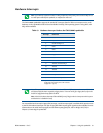
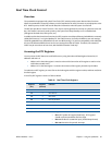
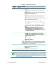
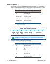
A list of key RTC registers is shown in Table 52 below:
.
Table 52 Real Time Clock Registers
Registers
(hex)
Registers
(decimal)
Function
00h 0 RTC Seconds
02h 2 RTC Minutes
04h 4 RTC Hours
06h 6 RTC Day of Week
07h 7 RTC Day of Month
08h 8 RTC Month
09h 9 RTC Year
0Ah 10 RTC Status Register A
• Bit 7: RTC Update In Progress (Read Only) - RTC registers
should not be accessed when this bit is high.
• Bits 6-4: Divider for 32.768 KHz input (should always be 010)
• Bits 3-0: Rate select for periodic interrupt.