


38 CMX158886 cpuModule BDM-610000049 Rev G
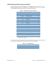
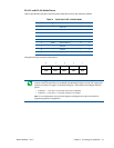
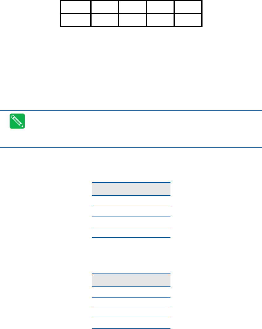
Facing the serial port’s connector pins, the pinout is:
RS-422 or RS-485 Serial Port
You may use Setup to configure the serial ports as RS-422 or RS-485. In this case, you must connect the serial
port to an RS-422 or RS-485 compatible device.
When using RS-422 or RS-485 mode, you can use the serial ports in either half-duplex (two-wire) or full-duplex
(four-wire) configurations. For half-duplex (2-wire) operation, you must connect RXD+ to TXD+, and connect
RXD– to TXD–.
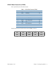
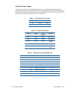
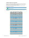
When using full-duplex (typically in RS-422 mode), connect the ports as shown in Table 19.
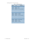
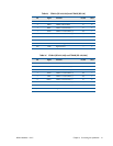
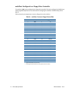
When using half-duplex in RS-485 mode, connect the ports as shown in Table 20.
9 7531
GND DTR TXD RXD DCD
GND RI CTS RTS DSR
108642
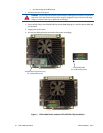
Note The cpuModule has a 120 Ω termination resistor. Termination is usually necessary on all RS-422
receivers and at the ends of the RS-485 bus.
Note If required, the termination resistor can be enabled by closing jumper JP1 for Serial Port 1
(COM1),JP2 for Serial Port 2 (COM2), JP11 for Serial Port 3 (COM3), and JP13 for Serial Port 4 (COM4).
Table 19 Full-Duplex Connections
Port 1 Port 2
RXD+ TXD+
TXD+ RXD+
RXD– TXD–
TXD– RXD–
Table 20 Half-Duplex RS-485 Mode
From To
Port 1 TXD+ Port 1 RXD+
Port 1 TXD– Port 1 RXD–
Port 1 TXD+ Port 2 RXD+
Port 1 RXD– Port 2 TXD–