


BDM-610000049 Rev G Chapter 3: Connecting the cpuModule 29
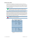
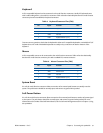
Keyboard
A PS/2 compatible keyboard can be connected to the multi-function connector. Usually PC keyboards come
with a cable ending with a 5-pin male PS/2 connector. Table 9 lists the relationship between the multi-function
connector pins and a standard PS/2 keyboard connector.
To ensure correct operation, check that the keyboard is either an AT compatible keyboard or a switchable XT/AT
keyboard set to AT mode. Switchable keyboards are usually set by a switch on the back or bottom of the
keyboard.
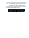
Mouse
A PS/2 compatible mouse can be connected to the multi-function connector. Table 10 lists the relationship
between the multi-function connector pins and a standard PS/2 mouse connector.
System Reset
Pin 3 of the multi-function connector allows connection of an external push-button to manually reset the
system. The push-button should be normally open, and connect to ground when pushed.
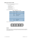
Soft Power Button
Pin 4 of the multi-function connector allows connection of an external push-button to send a soft power signal
to the system. The push-button should be normally open, and connect to ground when pushed. For more
information on the modes of the Soft Power Button, refer to the Power Management section in Chapter 4, Using
the cpuModule.
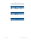
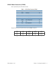
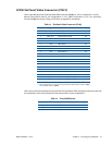
Table 9 Keyboard Connector Pins (CN5)
Pin Signal Function PS/2
5KBDKeyboard Data 1
6KBCKeyboard Clock 5
7 GND Ground 3
2 PWR Keyboard Power (+5 V) 4
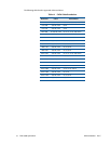
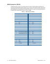
Table 10 Mouse Connector Pins (CN5)
Pin Signal Function PS/2
10 MSD Mouse Data 1
8MSCMouse Clock 5
7 GND Ground 3
2 PWR Keyboard Power (+5 V) 4