


BDM-610000049 Rev G Chapter 3: Connecting the cpuModule 33
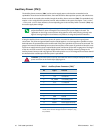
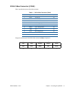
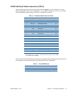
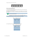
LVDS Flat Panel Video Connector (CN19)
Table 13 provides the pinout of the Flat Panel Video connector (CN19). FP_VCC is configured for +3.3V by
default. Contact RTD to have FP_VCC configured for +5 V. FP_VBKLT can be either +5 V or +12 V, and can be
selected with JP9. See Jumper Settings and Locations on page 86 for more details.
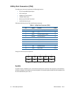
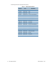
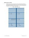
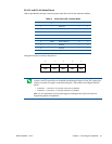
Table 14 lists several LVDS panels that were tested with this cpuModule. When evaluating a panel to be used with
this cpuModule, review the specifications of the tested panels to assure compatability.
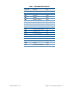
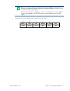
Table 13 Flat Panel Video Connector (CN19)
Pin Signal Function In/Out
1 Y0P LVDS Data 0+ out
2 Y0M LVDS Data 0- out
3DDC_CLK
1
1. The DDC signals use a +3.3 V signal level, and are not +5 V tolerant.
Panel Detection Clock out
4 GND Ground GND
5 Y1P LVDS Data 1+ out
6 Y1M LVDS Data 1- out
7 DDC_DATA
1
Panel Detection Data in/out
8 GND Ground GND
9 Y2P LVDS Data 2+ out
10 Y2M LVDS Data 2- out
11 GND Ground GND
12 GND Ground GND
13 YCP LVDS Clock+ out
14 YCM LVDS Clock- out
15 Y3P LVDS Data 3+ out
16 Y3M LVDS Data 3- out
17 GND Ground GND
18 FP_VCC
2
2. When configured for +3.3 V, FP_VCC is sourced from the auxiliary power connector (CN3)
or PC/104-Plus connector (CN16).
Power for flat panel electronics out
19 FP_VBKLT Power for flat panel backlight out
20 FP_ENABLK Enable for Backlight Power out
Table 14 Tested LVDS Panels
Manufacturer Model Number Resolution Color Depth
Optrex T-51756D121J-FW-A-AA 1024 x 768 18 bit
Optrex T-51639D084JU-FW-A-AB 1024 x 768 24 bit