


BDM-610000049 Rev G Appendix A: Hardware Reference 87
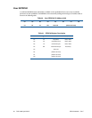
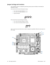
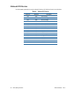
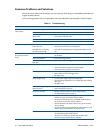
Figure 7 CMX158886 Jumper Locations (top side)
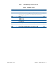
Table 62 CMX158886 Jumpers
Jumper Pins Function Default
JP1 2 Enable/disable 120 Ω series termination to COM1 (CN7) in RS-422/485 modes open
JP2 2 Enable/disable 120 Ω series termination to COM2 (CN8) in RS-422/485 modes open
JP5 2 Install to load the default BIOS settings and boot to Fail Safe (for more
information, refer to System Recovery—page 82). Note that the multi-color LED
will be red if JP5 is installed.
open
JP6 2Reserved open
JP9 3 Select power for flat panel backlight
pins 1–2: +12 V
pins 2–3: +5 V
pins 2–3
JP11 2 Enable/disable 120 Ω series termination to second serial port on CN7 in
RS-422/485 modes
open
JP12 2 Install to support RS-422/485 modes for second serial port on CN7 open
JP13 2 Enable/disable 120 Ω series termination to second serial port on CN8 in
RS-422/485 modes
open
JP14 2 Install to support RS-422/485 modes for second serial port on CN8 open