


64 CMX158886 cpuModule BDM-610000049 Rev G
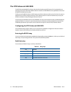
Port 1 Data register is a read/write byte direction
Interrupts
In order to use an interrupt with aDIO, the interrupt must first be selected in the BIOS setup utility under
Advanced, I/O Devices, aDIO Configuration, aDIO Interrupt. The Digital I/O can use interrupts 3, 5, 6, 7, 10,
11, and 12. The interrupt must also be reserved so that is it not assigned to PCI devices. To reserve the interrupt,
enter the BIOS under PCIPnP and change the interrupt you wish to use to “Reserved.” Then, select the
appropriate interrupt mode in the DIO Control register. Also, verify that the Int Mask bit is cleared in the Wake
Control register
Advanced Digital Interrupts
There are three Advanced Digital Interrupt modes available. These three modes are Event, Match, and Strobe.
The use of these three modes is to monitor state changes at the aDIO connector. Interrupts are enabled by
writing to the Digital IRQ Mode field in the DIO-Control register.
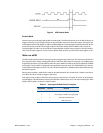
Event Mode
When this mode is enabled, Port 0 is latched into the DIO-Compare register at 8.33 MHz. The aDIO circuitry
includes deglitching logic. The deglitching requires pulses on Port 0 to be at least 120 ns in width. As long as
changes are present longer than that, the event is guaranteed to register. Pulses as small as 60 ns can register as
an event, but they must occur between the rising and falling edge of the 8.33 MHz clock. To enter Event mode,
set bits [4:3] of the DIO-Control register to “10”.
Match Mode
When this mode is enabled, Port 0 is latched into the DIO-Compare register at 8.33 MHz. The aDIO circuitry
includes deglitching logic. The deglitching requires pulses on Port 0 to be at least 120 ns in width. As long as
changes are present longer than that, the match is guaranteed to register. Pulses as small as 60 ns can register as
a match, but they must occur between the rising and falling edge of the 8.33 MHz clock. To enter Match mode,
set bits [4:3] of the DIO-Control register to “11”.
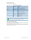
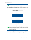
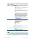
Table 50 Wake Control I/O Address 451h
D7 D6 D5 D4 D3 D2 D1 D0
Reserved Int Mask
1 = Interrupt is masked
0=Interrupt is enabled
Wake Enable
1=Interrupt triggers a Wake Event
0=Interrupt does not trigger a wake event.
Note Make sure bits [4:3] are set BEFORE writing the DIO-Compare register. If you do not set them first,
the contents of the DIO-Compare register could be lost because the Event mode latches in Port 0 into the
DIO-Compare register.