


76 CMX158886 cpuModule BDM-610000049 Rev G
Multi-Color LED
The CMX158886 has a Multi-Color LED located beside the EIDE connector (CN10) which can be enabled or
disabled in the BIOS setup screen. The color of the LED indicates the status of the board, as shown in Table 54.
The LED can also be controlled manually by writing to I/O Port 456h, as shown in Table 55 and Table 56.
The following table lists the color displayed and the value written.
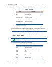
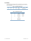
Table 54 LED Colors
Color Description
Green Normal Operation
Blue On Board IDE Activity
Red cpuModule is in reset
1
1. If power is applied to the cpuModule while jumper JP5 is installed, the LED will be red. This does not
indicate that the board is in reset
Yellow (Red + Green) cpuModule is in Standby
White (R+G+B) cpuModule is approaching thermal limit
2
2. The LED will remain White until the system is shut down.
Cyan (Blue + Green) Ethernet Link at 10 Mbps
Magenta (Blue + Red) Ethernet Link at 100 Mbps
Blink Ethernet Activity
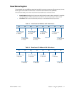
Table 55 Multi-Color LED I/O Address 456h
D7 D6 D5 D4 D3 D2 D1 D0
Reserved
(User
EEPROM)
Reserved
(User
EEPROM)
Reserved
(User
EEPROM)
Reserved Reserved Multi-Color LED
Note When writing to I/O Port 456h, only the lower three bits of the register should be modified.
Modifying the upper bits will effect the User EEPROM
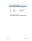
Table 56 Manual LED Colors
I/O Port 456h Value Color
0x00 Automatic (see Table 54)
0x08 Off (will reduce system power consumption.)
0x09 Blue
0x0A Green
0x0B Cyan (Green + Blue)
0x0C Red
0x0D Magenta (Red + Blue)
0x0E Yellow (Red + Green)
0x0F White (Red + Green + Blue)