


BDM-610000049 Rev G Chapter 3: Connecting the cpuModule 37
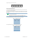
Serial Port 1 (CN7) and Serial Port 2 (CN8)
Serial Port 1 (COM1) is implemented on connector CN7, and Serial Port 2 is implemented on connector CN8.
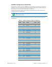
The serial ports are normally configured as PC compatible full-duplex RS-232 ports, but you may use the BIOS
Setup program to reconfigure these ports as half-duplex RS-422 or full-duplex RS-422 or RS-485. If you
reconfigure the ports, you must also select the I/O address and corresponding interrupt using Setup. Table 17
provides the available I/O addresses and corresponding interrupts.
Serial Port UART
The serial ports are implemented with a 16550-compatible UART (Universal Asynchronous
Receiver/Transmitter). This UART is capable of baud rates up to 115.2 kbaud in 16450 and 16550A compatible
mode, and includes a 16-byte FIFO. Refer to any standard PC-AT hardware reference for the register map of the
UART. For more information about programming UARTs, refer to Appendix D.
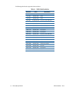
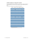
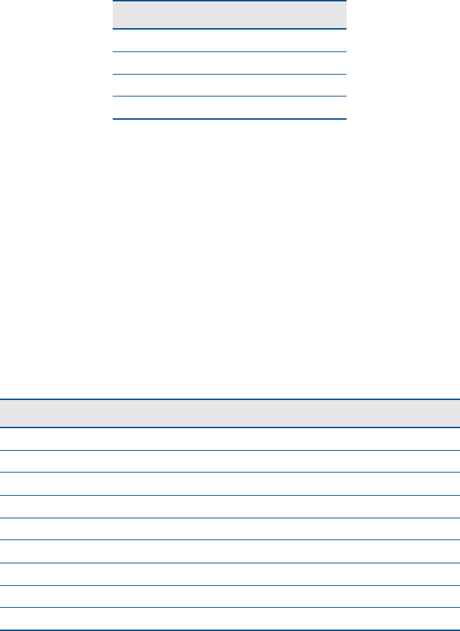
RS-232 Serial Port (Default)
The default serial port mode is full-duplex RS-232. With this mode enabled, the serial port connectors must be
connected to RS-232 compatible devices. Table 18 provides the serial port connector pinout and shows how to
connect to an external DB-25 or DB-9 compatible serial connector.
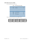
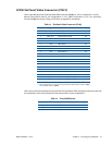
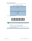
Table 17 Serial Port Settings
I/O Address (hex) IRQ
03F8 IRQ4
02F8 IRQ3
03E8 IRQ4
02E8 IRQ3
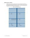
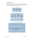
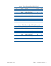
Table 18 Serial Port in RS-232 Mode
Pin Signal Function In/Out DB-25 DB-9
1 DCD Data Carrier Detect in 8 1
2DSRData Set Ready in66
3RXDReceive Data in32
4RTSRequest To Send out47
5 TXD Transmit Data out 2 3
6CTSClear To Send in58
7 DTR Data Terminal Ready out 20 4
8RIRing Indicate in229
9,10 GND Signal Ground — 7 5